
Why are transformer cores laminated? To stop eddy currents. Motor cores are laminated for the same reason. An alternating field induces circulating currents in any conductive core. In a solid block those currents run in large loops and turn energy into heat. Thin insulated sheets of electrical steel, also called silicon steel or lamination steel, cut the loops down to narrow paths that carry very little current.
The same few questions about this come up again and again on engineering forums. Would a solid core really be that bad? Do the sheets have to be insulated? Why is a squirrel-cage rotor laminated when it needs induced current to work? How do ferrite, toroidal and amorphous cores fit in? This article answers each one with the physics and the numbers. It also explains why that thin laminated steel has become one of the bottlenecks in the 2026 transformer shortage.
We’re Wuxi Zhongxin Special Steel (ZHX Steel). We supply grain-oriented and non-oriented electrical steel as coil and slit strip. If you’re choosing a grade rather than asking why it’s laminated, start with our guide on how to choose electrical steel.
Key Takeaways
- A solid iron core behaves like a shorted one-turn winding around the flux. It heats up and pushes the flux to its surface.
- At 50 Hz the field reaches only about 0.5 to 1.5 mm into electrical steel. That is why standard laminations are 0.23 to 0.50 mm thick.
- Laminations only work if they are insulated from each other. Burrs, welds or damaged coating that join sheets bring the loss back.
- Solid iron is fine where the flux doesn’t change, as in DC solenoids and DC contactors.
- A squirrel-cage rotor is laminated so that current flows in the aluminium or copper bars, not in the steel.
- Ferrite avoids eddy currents by not conducting. Amorphous cores use 0.025 mm ribbon, about a tenth of the thickness of transformer steel.
- Lead times for high-capacity transformers have reached as long as four years, and limited grain-oriented electrical steel is one of the main reasons. No other core material replaces it in large power transformers.
Why Not Use a Solid Iron Core?
Because a solid core is a conductor sitting inside a changing magnetic field. The changing flux induces a voltage around every loop inside the iron, and since iron conducts, current flows. A forum answer put it neatly: a solid core is effectively a shorted one-turn secondary.
That shorted turn does two kinds of damage.
- Heat. The circulating current flows through the iron’s resistance, so it dissipates power. An induction hob works on exactly this principle: the pan is a solid conductor in an alternating field, and it gets hot.
- Lost flux. The induced currents set up their own field, which opposes the applied one. The flux is pushed out toward the surface of the core, and the centre carries little of it.
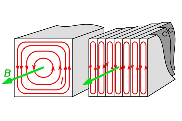
Engineers learned this early. Wikipedia’s history of the transformer records that early developers “soon realized that cores constructed from solid iron resulted in prohibitive eddy current losses.” Splitting the core into thin sheets parallel to the flux leaves the flux path intact but breaks the current loops. In each sheet the current can only circulate in a thin, elongated loop that encloses very little flux.
How Much Loss Would a Solid Core Add?
Far more than a laminated one, and you can’t calculate it with the usual lamination formula. That formula only holds when the sheet is thin compared with the depth the field reaches.
For a thin sheet, classical eddy-current loss is:
P = π² × B² × d² × f² / (6 × ρ × D)
where B is peak flux density, d is sheet thickness, f is frequency, ρ is resistivity and D is density. Wikipedia notes it is valid only when the frequency is low enough that there is no skin effect.
Using a resistivity of 46 µΩ·cm and a density of 7,650 kg/m³ for silicon steel, at 1.5 T and 50 Hz, the formula gives these values. They are our calculations, and they cover the classical eddy part only. Hysteresis and excess loss come on top.
| Sheet thickness | Classical eddy-current loss at 1.5 T, 50 Hz |
|---|---|
| 0.50 mm | 0.66 W/kg |
| 0.35 mm | 0.32 W/kg |
| 0.27 mm | 0.19 W/kg |
| 0.23 mm | 0.14 W/kg |
A solid 25 mm leg would come out at thousands of watts per kilogram on the same formula. That number is meaningless, because the formula has broken down. What actually happens is set by skin depth, the depth at which the induced currents have pushed the field down to about a third of its surface value.
Skin depth is δ = √(2ρ / (ω × μ)). Electrical steel has a relative permeability somewhere between 2,000 and 38,000 depending on grade and field strength. Taking 1,000 to 10,000 as a working range gives these results.
| Relative permeability | Skin depth at 50 Hz | Skin depth at 400 Hz |
|---|---|---|
| 1,000 | 1.53 mm | 0.54 mm |
| 2,000 | 1.08 mm | 0.38 mm |
| 5,000 | 0.68 mm | 0.24 mm |
| 10,000 | 0.48 mm | 0.17 mm |
This is the real reason for standard lamination thicknesses. At 50 Hz the field penetrates roughly half a millimetre to one and a half millimetres, so 0.23 to 0.50 mm sheets are fully used. In a solid 25 mm leg, only a thin layer at each face would carry most of the flux. That layer would saturate long before the core reached its design flux, and the induced current in it would run hot.
The same table shows why higher frequencies need thinner steel. At 400 Hz the skin depth falls to a few tenths of a millimetre, so 0.20 mm or thinner sheet is used. Our electrical steel thickness guide matches each gauge from 0.05 to 0.65 mm to its frequency range.
Do the Laminations Have to Be Insulated From Each Other?
Yes. If two sheets touch electrically along their faces, they act as one thicker sheet and the current loops join up again. Wikipedia’s transformer article puts it simply: each lamination “is insulated from its neighbors by a thin non-conducting layer of insulation.”
In practice the insulation is a thin coating applied at the steel mill, or on some small transformer laminations an oxide layer. A forum answer describing a small wall-plug transformer made the same point: its laminations had no separate sheets of paper between them, because the oxide layer on the electrical steel was the insulation. The coating classes and what each one tolerates are set out in our guide to electrical steel coating types.
Insulation can be lost in three common ways.
- Burrs. A sheet cut with tin snips or a worn punch leaves a raised edge. Pressed into the next sheet, it bridges the coating. One hobbyist who cut 150 E-shapes by hand described having to file an angle on every edge to stop sheet-to-sheet contact.
- Welds and clamps across the face. A weld bead along the side of a stack joins every sheet it crosses, so each one becomes a path for current between the sheets.
- Sanding or grinding. Removing rust from a stator bore with abrasive also removes coating. One hub motor owner did exactly this and then had to re-varnish the stator.
Insulation also takes a little space. The share of the stack height that is actually steel is the stacking factor, which we explain in lamination stacking factor explained.
When Is a Solid Iron Core Fine?
When the flux doesn’t change, or changes so slowly that eddy currents don’t matter. No change in flux means no induced voltage and no eddy current.
| Device | Flux | Core | Why |
|---|---|---|---|
| DC contactor or solenoid | Constant | Solid iron | Nothing to induce eddy currents; solid is stronger and cheaper |
| AC contactor | Alternating | Laminated silicon steel plus a shading ring | Changing flux would heat a solid core |
| Very high-speed solid-rotor induction motor | Alternating | Solid steel rotor | Mechanical strength at high speed outweighs the extra loss |
One forum answer made the contactor comparison: in large power contactors, you can tell which ones are DC controlled because the solenoid sits on a solid block of iron instead of a laminated stack. A contactor maker’s guide gives the same reasoning for the AC version: laminated silicon steel sheets insulated from one another break the path of eddy currents.
The high-speed rotor is the one deliberate exception for AC. A solid steel rotor can spin faster than a laminated one because it has no stack of thin sheets to fly apart. A US patent on cage motors for high rotational speeds gives an example limit of about 200 to 230 m/s peripheral speed for a laminated rotor core, to prevent it fracturing. It also notes that eddy currents on the surface of a solid rotor produce no torque and reduce efficiency. A second patent on solid-rotor machines says the same thing more directly: eddy current in a solid rotor produces a larger loss than in a laminated rotor and raises the rotor surface temperature.
Why Is a Squirrel-Cage Rotor Laminated If It Needs Induced Current?
Because the induced current is wanted in the bars, not in the steel. An induction motor works by inducing current in the rotor cage, the aluminium or copper bars joined by end rings. Those bars have low resistance, so they carry large currents and produce torque with little loss.
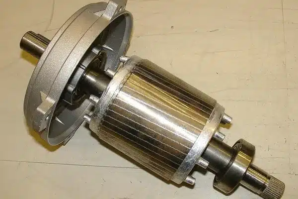
The steel around the bars has a different job: to carry flux. Steel is a poor conductor next to aluminium, so any current that flows in it does little useful work and a lot of heating. Laminating the core keeps current out of the steel and in the bars.
The rotor steel also sees a changing field, because an induction rotor turns slightly slower than the field. The frequency in the rotor is the slip frequency. At start-up the rotor is stationary and sees the full supply frequency. Slot openings and winding harmonics add higher-frequency ripple on top. A solid rotor would heat badly at start and lose efficiency in running.
There is a manufacturing reason as well. The rotor lamination is punched from the disc left in the centre of the stator lamination, so a laminated rotor costs very little extra material. For prototypes, before any die exists, we compare laser cutting, stamping and wire EDM in our article on cutting prototype motor laminations.
What about permanent-magnet rotors, which turn in step with the field? One forum reply claimed they don’t need laminations at all. That is too strong. Wolnik and Jarek (2022) compared a solid rotor core with a laminated M400 core in a 50 kW fractional-slot PMSM, a type in which magnetomotive force harmonics cause rotor losses. The solid core was simpler and lighter, but its rotor losses were much greater. With the solid core the motor delivered 25.4 kW continuously at 4,800 rpm. The laminated core ran cooler and gave 27.8 kW at the same speed, and it extended the operating range to 6,000 rpm and 34.3 kW. Above 2,400 rpm the laminated version’s efficiency was 0.7 to 1.4% higher. For how the stator steel grade feeds into motor efficiency classes, see IE3 vs IE4 motor efficiency.
How Do Toroidal and Ferrite Cores Avoid the Problem?
They solve it in two different ways. A toroidal steel core is still laminated, just as a spiral. A ferrite core doesn’t conduct, so it needs no laminations at all.
Toroidal steel cores. Wikipedia describes the toroidal core as made from a long strip of silicon steel or permalloy wound into a coil. Each turn of strip is one lamination. Because the strip is continuous, the closed ring has none of the air gaps that an E-I core has where E and I pieces meet.
E-I cores and interleaving. In an E-I core the gap at each joint costs magnetizing current. Interleaving, alternating the orientation of the E and I pieces from layer to layer, spreads those gaps. Wikipedia notes that the E-I design tends to have more losses than other shapes but is very economical to manufacture. If the E’s are all stacked on one side and the I’s on the other, as in some chokes, a forum answer warns that an air gap is hard to avoid and the excitation current will be higher.
Ferrite. Ferrite is a magnetic ceramic with very low electrical conductivity, so eddy currents stay small without laminating. That is why ferrite cores are standard from a few tens of kilohertz upward. The cost is saturation. Wikipedia notes that ferrite saturates at a substantially lower flux density than laminated iron, so at 50 Hz a ferrite core would have to be several times larger than a steel one.
Powdered iron. Iron particles bonded with insulation give high resistivity in bulk. These cores sit in between, typically used in switch-mode supplies up to a few tens of kilohertz.
Thin electrical steel covers part of this middle ground. Wikipedia notes that some very thin steel laminations can operate up to 10 kHz, which is where our ultra-thin silicon steel grades are used.
How Can You Tell an Amorphous Core From a Laminated Steel Core?
Look at how the core is built and how thick the layers are.
| Feature | Amorphous core | Silicon steel core |
|---|---|---|
| Layer thickness | About 0.025 mm ribbon | 0.23–0.50 mm sheet |
| Construction | Wound from continuous ribbon | Stacked from cut sheets, or wound from strip |
| Typical shapes | Wound rectangular or C-cores | E-I, mitred stacked cores, wound toroids |
| Handling | Brittle after annealing; can’t be punched | Can be punched, sheared and slit |
| Typical use | Distribution transformers, always energized at light load | Every transformer and motor size |
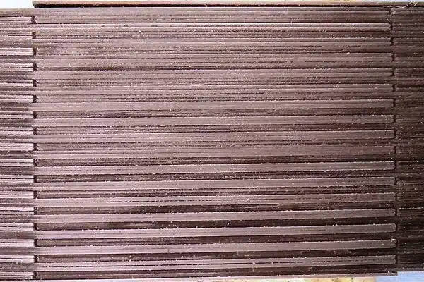
The thickness difference is the easiest sign. Metglas 2605SA1, a common amorphous alloy, is cast directly to a ribbon about 25 µm thick. A stack of it looks like a block of foil in which you can’t see separate layers. In a silicon steel core the separate sheets are clearly visible along the edge, as in the cover photo.
Amorphous metal is not used because it laminates better. It has no crystal structure, which gives it very low hysteresis loss. Metglas specifies 2605SA1 at a maximum core loss of 0.17 W/kg at 60 Hz and 1.3 T, with a saturation induction of 1.56 T. The trade-offs are lower saturation, a brittle ribbon and a bulkier core. We cover them in amorphous steel core transformers: the manufacturing constraints.
One forum poster wanted to know which kind of core they had because they wanted pure iron for making crucible steel. Neither will do. Laminated cores are usually silicon steel with around 3% silicon, and amorphous core alloys are iron with boron, silicon and phosphorus. Neither is plain iron. Whether amorphous pays back its cost in a given transformer is a separate question, worked through in amorphous vs silicon steel transformer cost.
Why Is Lamination Steel a Bottleneck in the 2026 Transformer Shortage?
Because every power transformer core is built from the thin, insulated grain-oriented sheet described above, and only a limited number of mills make it. When demand for transformers jumps, the steel can’t be swapped for something easier to get.
The demand jump is well documented. pv magazine reported in May 2026 that lead times for high-capacity transformers in the US have reached as long as four years, according to PwC analysts. Wood Mackenzie data in the same report shows demand for generator step-up transformers rose 274% between 2019 and 2025, and demand for substation transformers rose 116%. The report names “the limited availability of grain oriented electrical steel and copper” as a major factor in the supply crunch.
The physics in this article explains why there is no quick workaround.
- Solid iron is ruled out at 50 or 60 Hz, for the eddy-current reasons above.
- Ferrite saturates far too low for a power-frequency core of that size.
- Amorphous ribbon suits distribution transformers but saturates at about 1.56 T against roughly 1.8 to 2.0 T for grain-oriented steel, and it can’t be punched or stacked like sheet. It is not a drop-in replacement in large power transformers.
- Non-oriented steel is the motor grade. Its loss along one direction is much higher than grain-oriented steel’s, so a transformer built from it would need a bigger, lossier core.
That leaves grain-oriented steel, rolled to 0.23 to 0.30 mm and coated, as the material large transformers depend on. We explain the supply side, including mill capacity and allocation, in why there’s a global grain-oriented electrical steel shortage.
Which Core Construction Fits Which Job?
| Core | How it limits eddy currents | Frequency range | Typical use |
|---|---|---|---|
| Solid iron | Doesn’t. Needs steady flux | DC | Solenoids, DC contactors, pole pieces |
| Silicon steel laminations, 0.35–0.50 mm | Thin insulated sheets | 50–60 Hz | Power and distribution transformers, industrial motors |
| Silicon steel laminations, 0.10–0.27 mm | Thinner sheets | Up to several hundred Hz, some to 10 kHz | High-efficiency transformers, EV and high-speed motors |
| Wound amorphous ribbon | 0.025 mm ribbon, low hysteresis | 50–60 Hz | Low no-load-loss distribution transformers |
| Powdered iron | Insulated particles | Up to tens of kHz | Switch-mode inductors |
| Ferrite | Non-conductive ceramic | Tens of kHz upward | High-frequency transformers, EMI filters |
What This Means When You Order Lamination Steel
If you’re buying steel for a core, the reasons above turn into three ordering decisions.
- Thickness from frequency. Use the skin depth logic above: 0.35 or 0.50 mm at mains frequency, thinner as frequency rises.
- Coating from your process. The insulation coating has to survive your cutting, stacking and any stress-relief anneal. Tell us how you’ll cut and join the stack.
- Type from the flux path. Motors and generators rotate the field, so they use non-oriented steel. We supply it as CRNGO steel coil and slit strip.
Transformers and reactors carry flux in one direction, so they use grain-oriented steel, available as CRGO steel coil. Send your application, frequency and core size with your inquiry and we’ll recommend a grade and thickness.
Bottom Line
- Why laminate: a solid core is a shorted turn. It heats and pushes the flux to its surface.
- Why that thickness: at 50 Hz the field penetrates about 0.5 to 1.5 mm, so 0.23 to 0.50 mm sheets are fully used.
- Why insulate: sheets that touch act as one thick sheet. Burrs, welds and sanding undo the lamination.
- When solid is fine: steady DC flux, or very high-speed rotors where strength matters more than loss.
- The alternatives: ferrite doesn’t conduct, and amorphous ribbon is a tenth as thick, but both give up saturation flux density.
- Why it matters now: large power transformers have no substitute for laminated grain-oriented steel, which is why its limited supply feeds into lead times of up to four years.
Cover photo: interleaved E-I transformer laminations. Roy McCammon, Wikimedia Commons, CC0. Diagram: Chetvorno, Wikimedia Commons, CC0. Rotor photo: Zureks, Wikimedia Commons, CC BY-SA 3.0.
FAQ
Why are transformer cores laminated?
To reduce eddy-current loss. An alternating field induces circulating currents in a conductive core. Thin sheets insulated from each other confine those currents to narrow loops that carry little current. A solid core would heat up, waste energy and push the flux toward its surface.
What would happen if a transformer core were not laminated?
It would run hot and inefficiently. The solid core acts like a shorted turn, so induced current circulates through the iron and dissipates power. The induced field also pushes flux toward the surface, so most of the core section does little work and the surface layer saturates early.
Why are motor stators and rotors laminated?
For the same reason as transformers. The stator sees a rotating field, and the rotor sees slip-frequency flux plus harmonics. Laminating both keeps current out of the steel. In an induction motor it also forces the useful induced current into the aluminium or copper cage bars.
Do laminations need insulation between them?
Yes. If sheets touch electrically, they behave as one thicker sheet and the eddy-current loops rejoin. The insulation is a thin mill-applied coating or, in some small transformers, an oxide layer. Burrs, weld beads across the stack and sanding can all short sheets together.
Why don’t ferrite cores need laminations?
Ferrite is a ceramic with very low electrical conductivity, so eddy currents stay small without laminating. That suits it to frequencies from tens of kilohertz upward. Its saturation flux density is much lower than silicon steel’s, so it is not used for mains-frequency power transformers.
Can I buy laminated core steel in small quantities?
Yes, as slit strip or cut sheet from a coil, though prices per kilogram are higher than for full coils. Our guide on where to buy electrical steel in small quantities compares mills, distributors and service centres.
Need lamination steel for a transformer or motor core? Request a quote with the application, frequency and thickness.
References
- Wikipedia — Eddy current: power dissipation and skin depth
- Wikipedia — Transformer: laminated steel cores, toroidal cores, ferrite and powdered iron cores
- Wikipedia — Permeability (electromagnetism): values for some common materials
- Wikipedia — Electrical resistivity and conductivity: resistivity of various materials
- VIOX Electric — AC vs DC contactors: understanding their types and functions
- US Patent 6,566,778 B1 — Cage-type induction motor for high rotational speeds
- US Patent 11,489,424 B2 — Squirrel-cage induction rotating electrical machine, solid rotor, and design method
- Wolnik, T. and Jarek, T., Energies 15(15), 2022 — Solid Rotor Core vs. Lamination Rotor Core in Fractional-Slot PMSM Motor with High Power Density
- Metglas — 2605SA1 magnetic alloy data sheet
- Wikipedia — Amorphous metal transformer
- pv magazine USA, Ryan Kennedy, 11 May 2026 — U.S. transformer market faces severe supply constraints as lead times extend to four years


