
Key Takeaways
- Amorphous metal has no crystalline grain structure at all — it’s produced by cooling molten alloy at roughly a million degrees Celsius per second, which is the source of its low core loss and the reason it can’t be processed like grain-oriented electrical steel (CRGO).
- Common transformer-grade amorphous alloy saturates at roughly 1.56 Tesla, against roughly 1.8-2.0 Tesla for standard CRGO — a real physics constraint that requires a larger core cross-section for the same power rating, independent of cost.
- Amorphous ribbon is cast at approximately 25 microns (0.025mm) thick, versus CRGO’s typical 0.23-0.30mm lamination gauge — thin and brittle enough that it cannot be stamped or stacked the way CRGO laminations are; amorphous cores are wound, not built from cut laminations.
- These are geometry and process constraints, not just cost constraints — a transformer designed around a CRGO core cannot simply have amorphous ribbon substituted into the same physical footprint; the core has to be redesigned around amorphous’s lower saturation flux density and different construction method.
- Amorphous’s 50-70% no-load loss reduction versus CRGO makes it the right choice for lightly loaded, always-energized distribution transformers — the tradeoff and payback math for that decision is covered in depth in our sister analysis, Amorphous Core vs. Grain-Oriented Electrical Steel: A TCO Comparison.
What Makes Amorphous Metal Different From CRGO
Amorphous metal is a metal alloy with no crystalline structure at all. Its atoms sit in a disordered, glass-like arrangement instead of the ordered lattice found in conventional metals. That’s the whole story, metallurgically: it’s produced by cooling molten iron-based alloy at a rate of roughly one million degrees Celsius per second — fast enough that the atoms never get the chance to arrange into the crystal grains that form during conventional steel cooling.
CRGO (cold-rolled grain-oriented electrical steel) works in the opposite direction: it’s specifically processed — through repeated cold rolling and high-temperature annealing — to grow large, aligned crystal grains oriented along the rolling direction, because that grain alignment is what gives CRGO its low core loss along the magnetization axis. Amorphous metal skips grain formation entirely, and the absence of grain boundaries is precisely what gives it a core loss advantage over CRGO — grain boundaries are a significant source of the eddy current and hysteresis losses that occur every time a transformer core’s magnetic domains flip with the AC cycle.
The result: amorphous cores typically show 50-70% lower no-load (core) loss than equivalent CRGO cores. That number gets most of the attention in amorphous-vs-CRGO comparisons — but it’s the metallurgical cause behind that number, not the number itself, that explains why amorphous can’t simply substitute for CRGO in an existing transformer design.
The Saturation Flux Density Tradeoff Nobody Puts on the Spec Sheet
The same disordered atomic structure that eliminates grain-boundary losses also lowers amorphous metal’s saturation flux density — the maximum magnetic flux density the material can carry before it stops behaving as an effective magnetic conductor.
Common transformer-grade amorphous alloy saturates at approximately 1.56 Tesla. Standard CRGO grades saturate in the range of roughly 1.8 to 2.0 Tesla, depending on grade. That’s a real gap — not a rounding difference. And it directly determines how much core cross-sectional area is needed to carry a given magnetic flux without saturating.
Because flux density and cross-sectional area trade off directly against each other for a fixed power rating, a core built from amorphous metal needs a meaningfully larger cross-section — commonly cited in transformer design literature as roughly 25-30% more core cross-sectional area — to carry the same flux that a CRGO core carries in a smaller footprint. That’s a real, physics-driven design constraint, not a cost issue: even if amorphous ribbon were priced identically to CRGO, a transformer built around it would still need a larger, differently proportioned core.
Why Amorphous Ribbon Can’t Be Stamped Like CRGO
Standard CRGO for transformer laminations is typically supplied in the 0.23-0.30mm gauge range, with ultra-thin grades (used for high-frequency designs) available down to roughly 0.10-0.20mm. Amorphous ribbon, by contrast, is cast at approximately 25 microns (0.025mm) — roughly a tenth the thickness of standard CRGO, and thinner even than the specialty ultra-thin CRGO grades used for high-frequency applications.
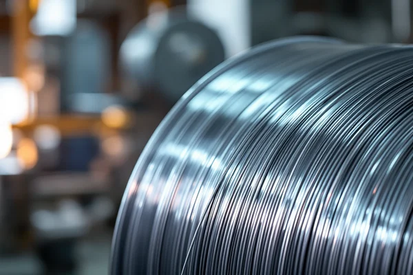
That thinness comes with brittleness. It’s the same property trade-off as the loss numbers: the disordered atomic structure that kills core loss also kills ductility. Amorphous ribbon doesn’t tolerate the punching, stamping, and stacking process used to build conventional laminated cores — try it, and it cracks. So amorphous cores are wound, not stacked: continuous ribbon wrapped around a form, not individual laminations cut and stacked by hand or press. That’s a fundamentally different construction method. Different tooling. Different manufacturing know-how. A different core geometry entirely — typically wound rectangular or C-core designs, not the stacked E-I or L-L laminations common in CRGO cores.
This is also why amorphous cores show a lower stacking factor than CRGO cores — commonly in the 80-88% range, against CRGO’s typical 92-97% — since wound ribbon construction inherently leaves more inter-layer gap than precision-stacked laminations. A lower stacking factor means, again, that more physical core volume is needed to achieve the same effective magnetic steel volume, compounding the saturation flux density constraint above.
What This Means for Core Design, Not Just Cost
Financial comparisons of amorphous versus CRGO — including the payback-period analysis in our own TCO comparison — correctly treat the decision as an economic one once a transformer is being newly designed. What that framing doesn’t cover, and what’s easy to miss if the loss numbers are the only thing being compared, is that amorphous and CRGO aren’t interchangeable inputs to the same core design.
A transformer core engineered around CRGO’s ~1.8-2.0 Tesla saturation and 0.23-0.30mm lamination gauge cannot simply have amorphous ribbon substituted in at the same physical dimensions — the lower saturation flux density means the core would saturate at a lower operating flux than intended, and the different lamination thickness and stacking factor change the winding window and core loss calculations throughout the design. Amorphous transformers are engineered from the ground up around amorphous metal’s specific properties, not retrofitted from a CRGO design. This matters for buyers evaluating amorphous as an option: it’s a different transformer design, sourced and built differently, not a drop-in material substitution on an existing CRGO-based product line.
A concrete comparison: take two 500 kVA distribution transformer designs targeting the same rated flux density margin. The CRGO version’s core window is sized around a ~1.9 Tesla working point with laminations stacked to a 94-96% factor — a compact, well-established design with decades of stamped-core manufacturing behind it. Scale that exact core geometry down to amorphous metal’s ~1.56 Tesla saturation without any other change, and the core would run too close to saturation under normal load swings, with elevated harmonic distortion and localized heating as a result. The amorphous version instead needs a taller or wider core window, adjusted winding turns to compensate for the different flux path, and a wound (not stacked) construction sequence — which is exactly why amorphous transformers exist as their own product line with their own tooling, rather than as a swap-in option on a CRGO manufacturer’s existing core designs.
Where Amorphous Still Makes Sense
None of the above makes amorphous the wrong choice — it makes it the right choice for a specific application profile. Amorphous’s core-loss advantage matters most where a transformer runs continuously at low load: distribution transformers that stay energized 24/7 but carry relatively light load most of the time, where no-load loss (which is constant regardless of load) dominates total lifetime energy loss more than load loss does.
That’s a load-factor-driven economic question, and it’s the one our TCO comparison works through in detail — including the payback framework, the point at which load factor makes CRGO the better economic choice instead, and how recent DOE 2016 efficiency mandates have narrowed the incremental cost of amorphous cores in some transformer categories. The manufacturing constraints in this article explain why that economic calculation looks the way it does — the physics sets the boundaries the economics operates within.
Utility distribution networks are the most common real-world example: a distribution transformer serving a residential feeder might see meaningful load only a few hours a day, but it stays energized around the clock. Over a 20-30 year service life, that constant no-load loss compounds into a substantial share of total lifetime energy cost — enough that many utilities specify amorphous cores as standard for new distribution transformer purchases, even accounting for the larger physical footprint and different sourcing relationship it requires versus a CRGO-based design.
Verifying What You’re Actually Buying
We get variations of this question from buyers moving between the two product lines for the first time: “amorphous core” and “CRGO core” aren’t interchangeable specifications, and a generic “high efficiency” claim doesn’t confirm what actually matters. Worth verifying before ordering:
- Actual no-load loss test data for the specific unit, not a generic “50-70% reduction” figure — core loss varies by amorphous alloy grade, core geometry, and manufacturing quality, and a mill test certificate or factory test report should show the tested value for the actual unit being purchased.
- Confirmed stacking factor and core cross-section, since a lower stacking factor and larger required cross-section directly affect the transformer’s physical size and weight — relevant for installations with space constraints.
- Manufacturer experience with wound amorphous core construction specifically, since it’s a distinct manufacturing process from stamped-lamination CRGO core assembly, not an extension of the same production line.
The same mill test certificate discipline that applies to CRGO sourcing applies here — a specific test report tied to the actual core, not a datasheet describing the amorphous alloy family in general.
FAQ
Can amorphous metal be used in the same transformer design as CRGO?
Not without redesign. Amorphous metal’s lower saturation flux density (~1.56T versus CRGO’s ~1.8-2.0T) and different lamination geometry (25-micron ribbon versus 0.23-0.30mm CRGO laminations) mean a core sized and shaped for CRGO cannot simply have amorphous substituted in — the core cross-section, winding window, and construction method all change when the design is built around amorphous metal instead.
Why is amorphous metal’s saturation flux density lower than silicon steel’s?
Amorphous metal’s disordered, glass-like atomic structure — the same property that eliminates grain-boundary losses and gives it a core-loss advantage — also reduces its saturation flux density compared to the ordered crystalline grain structure of CRGO. The two properties are linked: the metallurgical feature responsible for amorphous metal’s efficiency advantage is the same one responsible for its saturation limitation.
Is amorphous core loss reduction only about the material, or does construction matter too?
Both. The 50-70% no-load loss reduction versus CRGO comes primarily from the absence of grain boundaries in the amorphous structure, but the wound-core construction method (versus CRGO’s stacked laminations) and lower stacking factor also affect the final core’s performance and physical size. A buyer comparing loss numbers alone, without accounting for the resulting core geometry, is missing part of the picture.
Does a lower stacking factor make amorphous cores less efficient overall?
Not in terms of core loss — stacking factor affects the physical volume needed to achieve a given amount of magnetic steel, not the loss performance of the steel itself. A lower stacking factor (roughly 80-88% for amorphous versus 92-97% for CRGO) means the finished core is physically larger for the same magnetic cross-section, which is a size and material-cost consideration rather than an efficiency one.
References
- Metglas, Inc. — Frequently Asked Questions: Amorphous Metal Ribbon Specifications
- Metglas, Inc. — Amorphous Metal Transformer Core Technical Bulletin
- ASTM International — A719/A719M Standard Test Method for Lamination Factor of Magnetic Materials
- Nickel Institute — Nickel Alloys
- Zhongxin Special Steel (zhxsteel.com) — Amorphous Core vs. Grain-Oriented Electrical Steel: A TCO Comparison

