
Motor lamination stamping is punching rotor and stator laminations from electrical steel coil in a hardened die, usually a progressive die for volume production. The part price is low once the die exists, but the quality of every lamination depends on three things the buyer can control: the burr limit written on the drawing, the die clearance and regrind practice the stamper uses, and the steel that goes into the press. This guide covers each one and ends with what to put in a stamping RFQ.
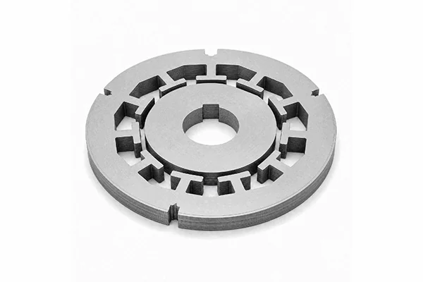
If you are still at the prototype stage, our guide to prototype motor laminations compares laser, wire EDM and stamping on tooling cost and edge damage. This article starts where that one stops: the design is frozen and the volume justifies a die.
Key Takeaways
- Progressive dies suit high volumes. Compound dies and notching cost less to tool and suit larger laminations or smaller runs.
- A common shop rule caps burr at 10% of sheet thickness. Our slitting limits are 10% at 0.35–0.50 mm and tighter at thinner gauges. Write the limit and the measurement method on the drawing.
- Burrs bridge the insulation between sheets. In a Cardiff study, artificial burrs pushed local loss in a transformer core above 1,000 W/kg at 1.8 T.
- Die clearance advice conflicts: one tooling engineer recommends about 10% of thickness for die life, while a 2021 study found 3% gave the lowest loss on M350-50A.
- Carbide dies run about 10 million parts before wearing out, against 2–3 million for D-2 tool steel, in one engineer’s estimates. Organic coatings can stretch die life further.
- Below about 0.25 mm the strip feeds like ribbon. Thin EV gauges need different die layouts, feeding and flatness checks.
Which Stamping Method Suits Your Volume?
Progressive stamping for high volume, compound stamping for medium runs and larger parts, and notching when the lamination is large and the run is short.
| Method | How it works | Best for | Trade-off |
|---|---|---|---|
| Progressive die | Strip moves through several stations; slots, bore and outline are cut in sequence, often with interlocking in the same die | High-volume stators and rotors | Highest die cost and setup |
| Compound die | Several features cut in one stroke at one station | Medium runs, medium and large laminations, very thin gauges | Slower than progressive |
| Rotary notching | A blank is indexed and slots are punched one at a time | Large laminations at lower tooling cost | Slower, may not match progressive precision |
Lamistacks, a lamination stamper, describes progressive stamping as “renowned for its high efficiency in high volumes production,” compound stamping as “well-suited for creating medium and large lamination,” and rotary notching as the way to “produce large laminations at reduced costs.” Laser Technologies Inc., a US stamper, suggests compound dies for gauges below 0.008 in (about 0.20 mm).
Many motor makers avoid a new die altogether. An engineer at a motor manufacturer explained on Reddit that “lamination tooling is expensive, so very often for more standard designs we use our standard laminations” and change the stack length and winding instead. If an existing lamination from your stamper’s catalogue is close enough, ask for it before paying for a new die. Our prototype guide shows how die cost compares with laser cutting at different volumes.
How High Can the Burr Be?
Low enough that it cannot bridge the coating between sheets, and that usually means a stated limit of 10% of thickness or less. No standard in our sources sets one figure for every lamination. The limit is agreed between buyer and stamper, so it has to be on the drawing.
Where the numbers come from. The old shop rule for stampings in general is that burr height should not exceed 10 percent of sheet thickness. Peter Ulintz, writing in MetalForming magazine in 2013, traced that rule back to an 1897 die-making book and argued it only holds for thin, low-carbon steel, so parts should get an engineered limit instead. For laminations, buyers usually ask for less than 10%. Our own slit-strip limits are 10% of thickness for 0.35–0.50 mm, 8% for 0.23–0.35 mm, 6% for 0.20–0.23 mm, and an absolute 0.01–0.02 mm for ultra-thin gauges. Our guide to slitting tolerances and camber explains why the limit tightens as the steel gets thinner.
| Thickness | 10% rule | Typical tighter limit for laminations |
|---|---|---|
| 0.50 mm | 0.050 mm | 0.050 mm (10%) |
| 0.35 mm | 0.035 mm | 0.028–0.035 mm (8–10%) |
| 0.27 mm | 0.027 mm | 0.022 mm (8%) |
| 0.20 mm | 0.020 mm | 0.012 mm (6%) |
How to measure it. IEC 60404-9 sets the methods for measuring geometric characteristics of electrical steel, including burr height. Its 2018 edition clarified that burr height is characterized by the maximum value, and added a procedure using a hand-held micrometer. Name the method on the drawing so the stamper and your incoming inspection measure the same thing.
Why it matters. A burr can pierce the thin insulation coating and touch the next sheet. Current then flows across the stack instead of being stopped at every layer, which defeats the whole reason for laminating the core.
- Mazurek et al., Cardiff University, 2012: artificial burrs on a 350 kVA three-phase transformer core raised local loss to over 1,000 W/kg in the most heavily burred region at 1.8 T, 50 Hz. Loss also rose outside the burred area.
- Shah et al., ICEMS 2017: in an EI core, interlaminar contacts on one limb raised the eddy-current loss coefficient by about 2%, and contacts on two limbs by about 2.7%.
The two results differ in size because the burrs differ. A few small contacts add a little loss. Burrs along many laminations can create large local hot spots. Burrs also add height to every sheet, which lowers the stacking factor. Our article on lamination stacking factor shows how much core height that costs.
What Die Clearance Suits Electrical Steel?
There is no single answer, and the published advice points in two directions. Clearance is the gap between punch and die, usually given as a percentage of sheet thickness per side.
The die-life view. Thomas Vacca of Micro Co., writing in The Fabricator in 2022 about stamping M19, recommends “a high clearance between the punch and die (about 10% of material thickness)” because silicon steel is hard on tools. A larger gap lets the steel spring back so the punch rubs less on its way through and back out.
The magnetic-loss view. Füzer and colleagues in Košice, Slovakia, punched rings from 0.5 mm M350-50A at clearances of 1%, 3%, 5% and 7% of thickness, then measured loss up to 400 Hz. The 3% clearance gave the lowest loss up to about 300 Hz, above which 1% did better. Losses rose at 5% and 7%. The authors found that “the excess loss is observed as the most sensitive loss component to cutting clearance.”
| Clearance (per side) | What it favours | Source |
|---|---|---|
| About 10% of thickness | Punch wear and die life | Vacca, The Fabricator, 2022 |
| 5% | Traditional general rule; Dayton Progress says it is too small for high-strength steels | Dayton Progress, 2014 |
| 3% | Lowest loss on 0.5 mm M350-50A up to about 300 Hz | Füzer et al., Materials, 2021 |
| 1% | Lowest loss above about 300 Hz in the same study | Füzer et al., Materials, 2021 |
In our view, the buyer does not need to set the clearance. That is the toolmaker’s job. But the buyer should know the trade-off, because a die built for long life and a die built for low loss are not the same die. For a high-frequency or high-efficiency motor, ask the stamper what clearance they plan and whether a sample run can be loss-tested before the die goes into production.
How Long Does a Lamination Die Last?
Millions of strokes, but burr height rises as the cutting edges wear, so the useful life is set by your burr limit.
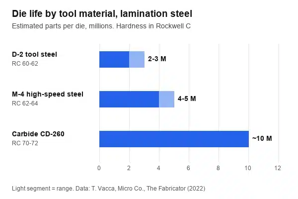
In the same Fabricator article, Vacca gives rough figures by tool material. D-2 tool steel at RC 60–62 suits orders around 200,000 parts and lasts 2 to 3 million parts. M-4 high-speed steel at RC 62–64 lasts 4 to 5 million. Carbide CD-260, at around RC 70–72, suits orders near 1 million parts and lasts about 10 million. He suggests titanium nitride coatings on steel punches and dies, and high-polished punches to cut friction. These are one engineer’s estimates, not measured data, but they show why high-volume lamination dies are usually carbide.
The steel coating matters too. thyssenkrupp states that its stabolit 10 insulation gives “up to three times longer die life compared with uncoated dry-punched electrical steel.” Organic coatings generally punch more easily than inorganic ones, but they do not survive stress-relief annealing as well. If you plan to interlock, weld or bond the stack, our guide to lamination stacking methods lists the coating that suits each one.
Two practical points follow:
- Agree a regrind trigger. Ask the stamper to regrind when burr reaches a set fraction of your limit, not when parts fail inspection.
- Keep the coating constant. Changing coating type or supplier mid-programme can change die wear and burr growth.
Which Steel Properties Make Lamination Stamping Harder?
Thickness, flatness, hardness and coating. The die is built for one gauge and one material, so variation in the coil shows up as variation in the laminations.
- Thickness and its tolerance. EN 10106 covers geometric tolerances for fully processed non-oriented steel in 0.35, 0.50, 0.65 and 1.00 mm. A die set up for one thickness cuts best when the strip stays close to nominal across the width and along the coil.
- Flatness and coil set. Strip that is not flat feeds badly and stacks poorly. Camber walks the strip off the die guides. Slit strip should arrive within agreed camber and edge-wave limits.
- Silicon content and hardness. Higher-grade, lower-loss grades generally carry more silicon. Silicon raises hardness and wear on the die, which is part of why Vacca recommends carbide for long runs.
- Coating type and weight. The coating affects die wear, as above, and also how well the stack can be welded or bonded later.
For the differences between non-oriented grades, including fully processed and semi-processed steel, see our guide to non-oriented electrical steel grades.
Why Is Thin-Gauge Stamping a 2026 Problem?
Because EV traction and other high-speed motors are pushing laminations thinner, and thin strip behaves differently in a die.
Laser Technologies Inc. noted in 2021 that EV makers were “starting to specify motor laminations that are in the .010″ range down to .004″ thick,” about 0.25 to 0.10 mm, against .014″ to .025″ for typical industrial laminations. Its tooling team wrote in 2025 that strip under 0.010 in behaves like ribbon: it can buckle at the lead edge or cling to guide rails. Their fixes include spring-loaded lifters between stations and pull-through pilots that drag the strip from the exit side.
Flatness is the other trap. The same article notes that designers often add a ±0.005 in flatness call-out without saying how it will be inspected. Laser Technologies checks parts under a clear plexiglass plate weighted at 1 to 5 lb before a vision reading, and recommends stating the inspection weight on the drawing. Narrow back iron, aggressive slot patterns and high-silicon alloys all make spring-back and flatness harder to hold.
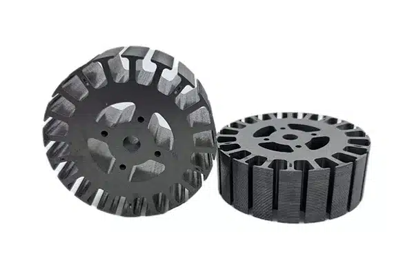
Not everyone agrees on how thin stamping can go. The UK Manufacturing Technology Centre considers stamping unsuitable below 0.2 mm, while some stampers run compound dies at 0.004–0.006 in. If your design is below 0.25 mm, ask for the stamper’s experience at that exact gauge. Our ultra-thin silicon steel page covers grades from 0.05 to 0.20 mm.
What Should a Lamination Stamping RFQ Include?
Everything that fixes quality, in one place. A complete motor lamination stamping RFQ gets comparable quotes and avoids arguments at first-article inspection.
| RFQ item | What to write | Why it matters |
|---|---|---|
| Drawing | DXF or STEP with tolerances on slots, bore and outline | Sets the die design |
| Grade and thickness | E.g. 35W300 or M300-35A, 0.35 mm, with guaranteed loss | Sets the steel and the clearance |
| Coating | Coating class and whether parts will be welded, bonded or annealed | Affects die wear and stacking |
| Burr limit | Maximum burr in mm and the method, e.g. IEC 60404-9 micrometer | The main lamination quality spec |
| Flatness | Value and inspection method, including any weight | Thin gauges need a stated method |
| Stacking | Interlock, weld, bond or loose; stack height tolerance | Decides die stations and coating |
| Volume | Annual quantity and batch size | Decides progressive vs compound vs notching, and die material |
| Die terms | Who owns the die, regrind trigger, expected life | Avoids surprises at the first regrind |
| Samples | First-article parts and, for critical motors, a loss test on a sample stack | Confirms the die before volume |
| Steel source | Supplied by stamper or by you; coil width or slit width | Lets you control grade and traceability |
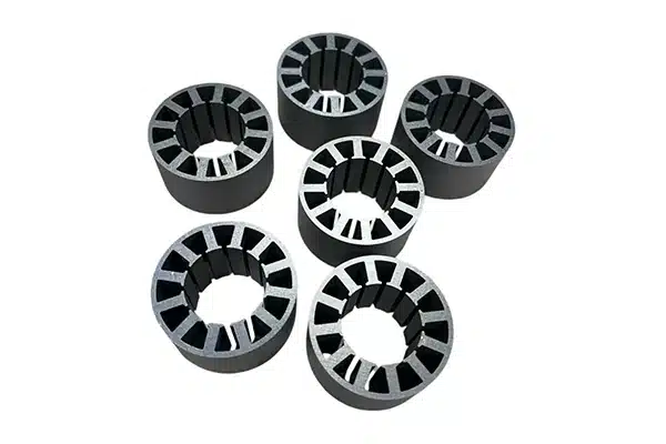
We supply non-oriented steel as CRNGO steel coil, slit strip and cut sheet, and we also stamp laminations to your drawing for production, so the steel and the stamping can be quoted together. Coil orders typically start at about 5 tonnes, and smaller lots can be cut from coil. Sheet orders typically start at about 500 kg; if you need less, tell us and we’ll do our best to meet the request. Samples typically cost USD 200 including freight, refunded when you place a production order.
FAQ
What is motor lamination stamping?
It is the process of punching rotor and stator laminations from electrical steel coil in a hardened die mounted in a high-speed press. Progressive dies cut slots, bore and outline in successive stations and often interlock the sheets into stacks in the same die. Compound dies and rotary notching are used for larger laminations, smaller runs or very thin gauges.
What burr height is acceptable for motor laminations?
A common rule for stampings caps burr at 10% of sheet thickness, which is 0.05 mm on 0.50 mm steel. Lamination buyers often ask for less, especially on thin gauges, for example 6–8% of thickness. There is no single standard limit, so write the maximum burr and the measuring method, such as IEC 60404-9, on the drawing.
What die clearance should be used for electrical steel?
It depends on what you optimise. One tooling engineer recommends about 10% of thickness per side to reduce punch wear on silicon steel. A 2021 study on 0.5 mm M350-50A found the lowest core loss at 3%, with higher loss at 5% and 7%. Ask the stamper what clearance they plan and whether a sample stack can be loss-tested.
How long does a lamination stamping die last?
In one engineer’s estimates, a D-2 tool steel die lasts about 2 to 3 million parts, M-4 high-speed steel about 4 to 5 million, and carbide about 10 million. The useful life depends on your burr limit, because burr rises as the edges wear. Organic steel coatings can extend die life; thyssenkrupp quotes up to three times for one coating.
Can 0.20 mm electrical steel be stamped?
Yes, but it is harder. Strip below about 0.25 mm feeds like ribbon and can buckle or cling to guides, so stampers use compound dies, lifters and pull-through pilots, and need a stated flatness check. Some research centres consider stamping unsuitable below 0.2 mm, while some stampers run thinner. Ask for experience at your exact gauge.
Planning a production run of motor laminations? Contact us with your drawing, grade, thickness, coating and annual volume, and we’ll quote the steel, the stamping, or both.
References
- Lamistacks, 13 May 2024 — Motor lamination stamping techniques
- Laser Technologies Inc., 6 August 2025 — Stamping ultra-thin laminations: feeding tricks, flatness specs and tooling trade-offs
- Laser Technologies Inc., 9 July 2021 — Thin gauge electrical steel for EV applications
- P. Ulintz, MetalForming Magazine, August 2013 — Defining acceptable burr height (Tooling by Design)
- IEC 60404-9:2018 — Magnetic materials – Part 9: Methods of determination of the geometrical characteristics of electrical steel strip and sheet
- R. Mazurek, H. Hamzehbahmani, A. J. Moses, P. I. Anderson, F. J. Anayi, T. Belgrand, IEEE Transactions on Magnetics 48(4), 2012, 1653–1656 — Effect of artificial burrs on local power loss in a three-phase transformer core
- S. B. Shah, P. Rasilo, A. Belahcen, A. Arkkio, ICEMS 2017 — Experimental and theoretical study of interlaminar eddy current loss in laminated cores
- T. Vacca (Micro Co.), The Fabricator, 22 December 2022 — What tool steel and coating are best for stamping lamination steel?
- J. Füzer, S. Dobák, I. Petryshynets, P. Kollár, F. Kováč, J. Slota, Materials 14(22), 2021, 6893 — Correlation between cutting clearance, deformation texture, and magnetic loss prediction in non-oriented electrical steels
- Fabricating & Metalworking, March 2014 — Optimizing punch-to-die clearance (Dayton Progress Engineered Clearance brochure)
- thyssenkrupp Steel — Insulation types for non-grain-oriented electrical steel
- EN 10106:2015 — Cold rolled non-oriented electrical steel delivered in the fully processed state
- Manufacturing Technology Centre (MTC) — Water jet guided laser: application and implementation
- Reddit threads behind this topic: r/EngineeringStudents (lamination tooling cost and standard laminations), r/Motors and r/diyelectronics (custom stator sourcing)


