
There are four main lamination stacking methods: interlocking, welding, adhesive bonding and self-bonding coating. Transformer cores add clamping and interleaving. Each method holds the stack together in a different way, and each adds a different amount of core loss. In published tests, welding added the most, interlocking less, and bonding the least. The method also decides which insulation coating you should order on the steel.
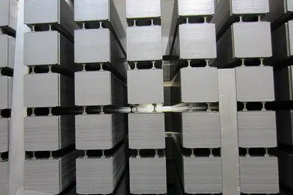
The questions below come from engineers and builders on engineering forums. One drone motor maker had laser cutting under control but found epoxy bonding “tougher”. A hub motor owner wanted to re-glue loose laminations. Others asked whether production stators are welded or interlocked, and how to hold loose E-I sheets together. If you’re still choosing the steel grade, start with our guide on how to choose electrical steel. This article covers what happens after the laminations are cut.
Key Takeaways
- Interlocking presses small dimples in each lamination into the one below, inside the stamping die. One study measured about 5% more iron loss than loose punched rings.
- Welding runs seams along the outside of the stack. In an Aalto University test, a laser-welded ring core lost 15–30% more than an unwelded one.
- Bonding glues every sheet to the next and leaves the insulation intact. Reviews rank it the least damaging method magnetically.
- Self-bonding coating (often called Backlack) is applied to the steel on the coating line and activated by heat and pressure after punching. It has to be ordered with the steel.
- Thin-gauge steel is harder to interlock or weld well, which is why EV and drone motor makers are looking at bonded stacks.
- Transformer cores are usually interleaved and clamped. Step-lap joints cut core loss by about 8% in one distribution transformer study.
Which Lamination Stacking Method Should You Use?
Use interlocking for most stamped production motors, welding when you need a strong stack at low cost, and bonding when losses, noise or thin gauges matter most.
| Method | How the stack is held | Added core loss in published tests | Strength | Typical use |
|---|---|---|---|---|
| Interlocking | Dimples punched into each sheet and pressed together in the die | Low to moderate; rises with the number of interlocks | Moderate; weaker when pulled apart along the stack axis | High-volume stamped stators and rotors |
| Welding (laser or TIG) | Seams along the outer surface | Highest of the common methods | High | Industrial motors, larger stators |
| Adhesive bonding | Glue dots or full-face adhesive between sheets | Lowest | Good, but adhesives can fatigue at high temperature | EV traction, high-efficiency motors |
| Self-bonding coating | Coating on the steel bonds under heat and pressure | Lowest | Good, full-face | Thin-gauge EV and drone motors |
| Riveting, bolting, clamping | Rivets, bolts or a frame through or around the stack | One study measured clamped cores between punched and welded ones | High | Larger machines, transformer cores |
Every method that creates an electrical path between sheets works against the reason cores are laminated in the first place. We explain that reason in why transformer and motor cores are laminated.
How Much Core Loss Does Each Stacking Method Add?
Somewhere between a few percent and about 30%, depending on the method, the number of joints and the frequency. The table collects measurements from studies we could read in full or in a peer-reviewed review.
| Study | What was compared | Result |
|---|---|---|
| Matsui and Yun, Gifu University, 2018 | 35A270 rings, 1.0 T, 50 Hz | Punching added 24% over wire-cut rings; interlocking added 5% on top of punching |
| Sundaria et al., Aalto University, 2020 | M400-50A ring cores, 13 laser weld passes, 50 Hz | Welded ring lost 15–30% more than unwelded |
| Sundaria et al., same paper | Complete industrial motor stator at rated voltage | Cutting, welding and shrink fitting together added 23%; welding’s share was about 7% |
| Study cited by Sundaria et al. | 120 W reluctance motor stators | Building factors of 1.22 punched, 1.30 clamped, 1.34 welded |
| AIP Advances, 2018 | Interlocked vs welded stacks | Loss from welding “much larger” than from interlocking |
| EuroGroup Laminations, 2019 (vendor data) | Glued vs interlocked, cleated or welded stators | 15% to 44% lower core loss with glue |
A building factor of 1.34 means the finished core lost 34% more than the steel’s catalogue value. The vendor figures are the company’s own tests, reported by Charged EVs, so treat them as an upper estimate until independent data appears.
Two patterns hold across the studies. First, more joints mean more loss. One study cited in a 2020 review found that iron loss rose linearly with the number of interlocks. Second, the penalty grows with frequency, because joints short the sheets together and eddy currents rise faster at high frequency. The catalogue loss on a mill certificate comes from an Epstein test on loose strips, which we explain in core loss testing on an Epstein frame. Your stacked core will always lose more than that number.
Cutting matters as much as joining. In the Gifu study, punching alone added more loss than interlocking did. We compare cutting methods in our guide to prototype motor laminations.
How Does Interlocking Work, and Why Is It the Default for Stamped Motors?
Interlocking, also called clinching or stitching, adds one more station to the stamping die. That station presses small dimples into each lamination. When the next lamination lands on top, its dimples push into the ones below, and the stack locks together inside the die.
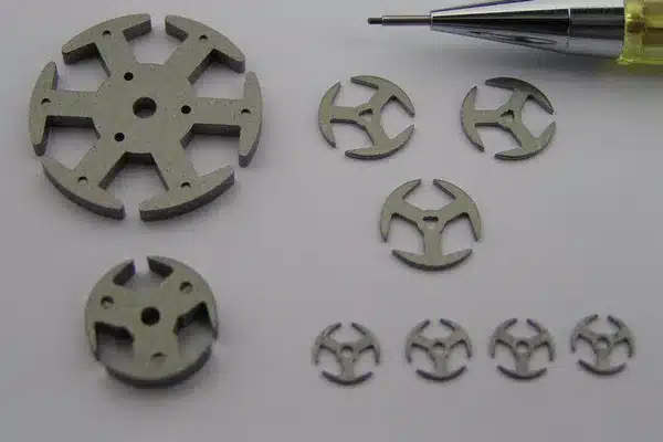
The appeal is cost. One motor manufacturer described it on a forum: with interlocked (“stitched”) laminations, a line can “run completely lights out”, with steel feeding in one end and finished stators coming out the other. No separate joining step, no oven and no welder.
The drawbacks come from the dimple itself.
- It shorts the sheets. The dimple pushes through the coating and puts steel against steel. Gifu University researchers found that interlocked areas can touch the sheet above, raising eddy current loss.
- It adds stress. The deformed metal around each dimple has higher hysteresis loss. Rectangular interlocks held better than circular ones in the 2018 AIP Advances study, but lost more.
- It is weaker along the stack axis. A 2020 review in Materials notes that interlocks are weaker perpendicular to the sheet and have a shorter fatigue life than welds.
- It gets harder on thin sheet. A coating maker notes that interlocking and welding are harder to achieve with thin-gauge steel. We come back to this below.
For interlocking, the steel needs a coating that punches cleanly and doesn’t wear the die. Coating maker Quaker Houghton positions its organic C3 coating for fast punching and says laminations with it “may be fixed by means of rivets, clamps or interlocking”.
When Does Welding Make Sense?
When the stack needs high strength and the extra loss is acceptable. Welding is common for industrial motors. The 2020 review calls fusion welding “the most reliable method to join the electrical steel laminations”.
The stack is loosely assembled and pressed, then welded with several seams along the outside diameter. TIG and laser welding are both used. The Aalto paper explains the two ways a seam adds loss.
- The seam shorts the sheets at the outer surface, creating local eddy currents. Heat from welding also adds thermal stress, which lowers permeability.
- Burrs make it worse. If cutting burrs have already bridged some sheets, the seam closes the loop and lets larger eddy currents flow through the whole stack. Depending on welding speed, the paper cites added loss of 5% to 20% from welding alone.
You can reduce the penalty. Use as few seams as the strength allows, keep heat input low, and keep burrs small. Studies summarised in the 2020 review found TIG welds caused more eddy current loss than laser welds, and pulsed laser spot welds did better than continuous seams.
Order a coating that tolerates welding. Quaker Houghton lists its C5 organic/inorganic coating as supporting “further annealing and welding processes”, whereas its C3 is aimed at interlocking and clamping.
Why Are EV and Drone Motor Makers Moving to Bonded Stacks?
Because their laminations are getting thinner, and thin laminations are hard to interlock or weld without losing what the thin steel was meant to gain. A 2024 Quaker Houghton brochure describes “a trend to use thinner, more complex core plate design”. It says traditional joining by interlocking, welding or clamping is “harder to achieve with thin-gauge steel and can impair magnetic performance”. Our ultra-thin silicon steel page covers the 0.05 to 0.20 mm range these motors use.
Bonding takes two forms.
- Adhesive applied during stamping. EuroGroup Laminations applies adhesive in the die. The company says it cures at room temperature in under 3 minutes and reduces acoustic noise by up to five times compared with interlocking.
- Self-bonding coating (Backlack). The steel arrives with a varnish that is dry to the touch but still reactive. voestalpine calls this the “B state”. After punching, the stacked laminations are heated under pressure and the varnish bonds every sheet to its neighbours, full-face.
The cure schedule is flexible. Quaker Houghton’s test data for its self-bonding varnish on 0.5 mm steel shows bonding at 3 MPa from 60 minutes at 140 °C to 2 minutes at 230 °C, with a 3.5 µm dry film. Faster cycles need higher temperature, and large stacks need time for the heat to reach the middle. voestalpine stresses that the whole stack must reach bonding temperature.
POSCO says welding degraded the electromagnetic performance of electrical steel, and that self-bonding reduces both core loss and the noise from gaps between sheets. Bonding has costs too.
- The coating must be ordered with the steel. It goes on at the coating line, not at the lamination shop.
- It has a shelf life. voestalpine specifies storage at around 23 °C, never above 40 °C, and use within six months of delivery.
- It needs a curing step. That means an oven or heated press, and time.
- Adhesives can fatigue at high temperature. The 2020 review calls this concern “the biggest obstacle” to wider use of glued cores.
How Do You Bond a DIY or Repair Stack?
Clamp evenly, use a thin adhesive layer, and keep the original coating intact. Forum builders run into the same three problems.
- Even clamping is hard. The drone motor builder tested “several fixturing and clamping methods” without being fully satisfied. A flat, rigid fixture with a central mandrel through the bore keeps teeth aligned and the stack square.
- Sanding removes the insulation. The hub motor owner sanded rust off a stator and took the protective layer with it. They ordered insulating varnish to recoat it. A commenter warned that a recoat must stay very thin, or it can upset the rotor-stator balance.
- Small transformers need less than you’d think. One forum answer noted that on small transformers, the oxide layer on the sheets is usually enough insulation. The assembled core is then varnished to hold it together and keep it quiet. Another suggested paraffin or enamel, which soften with heat or solvent for later disassembly.
For a prototype, buy steel that already has a coating rather than trying to insulate bare sheet. Our guide on where to buy electrical steel in small quantities covers sheet sizes and minimum orders.
How Are Transformer Cores Stacked?
Transformer cores are mostly interleaved and clamped rather than welded or glued. In an E-I core, the E and I pieces alternate direction from one layer to the next. Each butt joint is then bridged by full sheets above and below, so the flux can step around the gap.
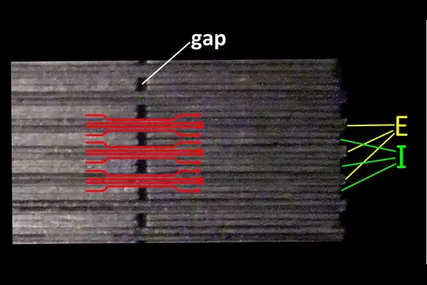
How many sheets you flip at a time matters. A forum member asked whether interleaving one sheet per layer beats stacking three or four together. One reply said interleaving with one lamination per “book” gives slightly lower loss, on the scale of 24 W down to 22 W on a small transformer. That is one person’s figure, not a test, but it shows the size of the effect: real, but small.
Large grain-oriented cores use mitred joints, often in a step-lap pattern. The joints of successive layers are offset in several small steps instead of one. A 2011 University of Moratuwa thesis, built around a transformer maker’s new step-lap cutting line, found that step-lap cores can cut distribution transformer core loss by about 8%. Our guide to power transformer core steel selection covers the grades these cores use.
Which Coating Should You Order for Each Stacking Method?
Match the coating to the joining method and to any annealing step. The classes below follow one coating maker’s product guidance, so check the datasheet of the steel you’re actually buying.
| Stacking method | Coating to ask for | Why |
|---|---|---|
| Interlocking, riveting, clamping | Organic C3 | Punches cleanly, long die life |
| Welding | C5 organic/inorganic | Tolerates welding heat |
| Stress-relief annealing after punching | C5 | Survives annealing temperatures |
| Large machines with high heat and pressure loads | C6 | Made for heat, pressure and vibration damping |
| Bonding in the stack | Self-bonding varnish (a C3-type bonding varnish) | Insulates and bonds in one layer |
| Adhesive dots applied in the die | Ask the lamination maker | Depends on the adhesive system |
Our article on electrical steel coating types explains what the coating classes mean.
Thicker coatings insulate better but take up more room in the stack. Our guide to lamination stacking factor shows how much space each class costs.
What Should You Tell Your Steel Supplier?
Tell them how the stack will be joined. The answer changes the coating, and sometimes the grade.
- Joining method. Interlocking, welding, glue in the die, self-bonding or clamping.
- Coating class and thickness. Name the class, or describe the process and let the supplier propose one.
- Annealing. Whether the laminations will be stress-relief annealed, and at what temperature.
- Grade and thickness. For example 35W300 at 0.35 mm, or the loss you need at your frequency.
- Form and size. Coil, slit strip or cut sheet, with width and tolerance.
- Certificate. A mill test certificate with measured loss and coating data.
We supply non-oriented steel as CRNGO steel coil, slit strip and cut sheet. We also cut laminations to your drawing, by laser for prototypes and by stamping for production. Tell us in the RFQ how the stack will be joined, and we’ll confirm the coating before we quote. Sheet orders typically start at about 500 kg. If you need less, tell us and we’ll do our best to meet the request. Samples typically cost USD 200 including freight, refunded when you place a production order.
FAQ
What are the main lamination stacking methods?
The main lamination stacking methods are interlocking, welding, adhesive bonding and self-bonding coating, plus riveting, bolting and clamping for larger machines and transformers. Interlocking is the usual choice for stamped production motors, welding for strong industrial stacks, and bonding for thin-gauge, low-loss motors such as EV traction and drone motors.
Does welding a stator stack increase core loss?
Yes. The weld seams short the laminations together and add thermal stress. In an Aalto University test, a laser-welded ring core lost 15 to 30% more than an unwelded one at 50 Hz. In a complete industrial stator, welding accounted for about 7% of total core loss. Fewer seams and lower heat input reduce the penalty.
Is interlocking or welding better for motor laminations?
For magnetic performance, interlocking usually wins: a 2018 study found the loss from welding “much larger” than from interlocking. Welding gives a stronger stack, especially along the stack axis. Interlocking is also cheaper in volume because it happens inside the stamping die, with no separate joining step.
What is Backlack or self-bonding electrical steel?
It is electrical steel with a self-bonding varnish applied on the coating line. The varnish is dry but still reactive. After punching, the stacked laminations are heated under pressure and the varnish bonds every sheet to the next. One maker’s data shows bonding from 60 minutes at 140 °C to 2 minutes at 230 °C.
How do I glue loose motor laminations back together?
Clean the stack, keep the original insulation intact, and use a thin adhesive or insulating varnish so the stack height barely changes. Clamp the laminations flat and evenly, ideally on a mandrel through the bore so the teeth stay aligned. If you sanded off rust, recoat the bare steel thinly before reassembly.
Does interleaving E-I laminations one at a time reduce losses?
Slightly. Alternating one E-I pair per layer bridges each butt joint more evenly than flipping groups of three or four. One forum reply put the difference at about 24 W versus 22 W on a small transformer. In large cores, step-lap joints do the same job and cut core loss by about 8% in one study.
Planning a motor or transformer core? Contact us with your grade, thickness, joining method and quantity, and we’ll quote the steel with the right coating, or the cut laminations.
References
- Matsui, T. and Yun, K., Gifu University, MATEC Web of Conferences 207, 03017, 2018 — Magnetic properties of silicon steel sheet core with different processing stress
- Sundaria, R. et al., Aalto University, IEEE Transactions on Energy Conversion, 2020 — Effects of manufacturing processes on core losses of electrical machines
- Xia, C. et al., Materials 13(20):4583, 2020 — Joining of the Laminated Electrical Steels in Motor Manufacturing: A Review
- Liu and Liu, AIP Advances 8, 2018 — Analysis of interlocking performances on non-oriented electrical steels
- Quaker Houghton — Insulating Coatings for Non-Grain Oriented Electrical Steel (brochure, 2024)
- voestalpine — Backlack self-bonding varnish
- Charged EVs, 2019 — EuroGroup’s new gluing technology promises to improve motor efficiency
- POSCO Newsroom, 2021 — e Autopos Unboxing 2: the secret of improving motor efficiency
- Gunawardhana, T.C.D.A., University of Moratuwa MSc thesis, 2011 — Analyzing economic benefit and performance of step-lap cores over conventional cores in distribution transformers
Image credits
- Generator stator core during assembly: Wtshymanski, Wikimedia Commons, CC BY-SA 3.0
- Stamped motor laminations: NVT Technology Pte Ltd, Flickr, CC BY-SA 2.0
- Interleaved E-I laminations diagram: Constant314, Wikimedia Commons, CC0


