
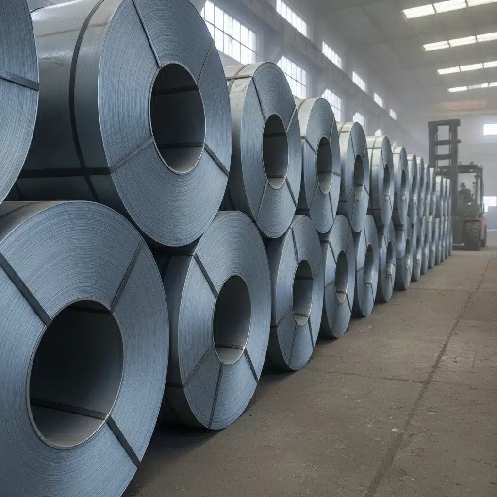
Most buyers asking “what is grain-oriented silicon steel” already have a transformer core spec in front of them and a supplier quoting a grade code they don’t fully trust. Fair enough — the short answer is this: grain-oriented silicon steel (GOES, also called CRGO — cold-rolled grain-oriented electrical steel) is a 3.0–3.5% silicon-iron alloy rolled and annealed so its crystal grains align almost entirely with the rolling direction. That alignment gives it high magnetic permeability and low core loss along one axis — exactly what a transformer core needs, since flux travels in a fixed direction around the loop. In practical terms, GOES is the material transformer manufacturers reach for whenever core efficiency, not just core strength, decides the design. Everything below is the data behind that answer — the grade tables, the loss numbers, and the things we get asked to explain on almost every sourcing call.
Key Takeaways
- What it is: A silicon-iron electrical steel with directionally aligned (Goss-textured) grains, used almost exclusively in transformer and reactor cores.
- Standard grades (our mill): 23Q110/M3, 27Q120/M4, 30Q130/M5, 35Q155/M6 — 0.23–0.35 mm thick, iron loss P1.7/50 from 1.05 to 1.55 W/kg.
- Hi-B and laser-scribed grades push iron loss down to 0.80–0.90 W/kg with B8 induction of 1.88–1.90 T.
- Stacking factor runs ≥0.95 on thin gauges (0.23–0.27 mm) and ≥0.97 on thicker gauges (0.30–0.35 mm) — it directly determines how much active steel actually sits inside a given core window.
- GOES is not the same material as non-oriented electrical steel (NOES/CRNGO), which is used in rotating machines because its properties are roughly uniform in every direction, not just one.
Why “Grain-Oriented” Matters for a Transformer Core
Ordinary steel has randomly oriented grains, so its magnetic properties are roughly the same in any direction — fine for a motor rotor that sees flux from multiple angles, wasteful for a transformer core where flux flows one way around a fixed loop. Grain-oriented silicon steel solves this by controlling the hot-rolling, cold-rolling and high-temperature annealing sequence (typically around 1200°C for secondary recrystallization) so that the [110]<001> crystal orientation — known as the Goss texture — dominates the finished sheet. Grains line up with the rolling direction, and magnetic flux moving along that same direction meets far less resistance than it would in non-oriented steel.
The payoff is measured in two numbers every transformer engineer checks first: core loss (how much energy is wasted as heat per kilogram of steel, per cycle) and magnetic induction (how much flux the steel carries before saturating). Grain orientation improves both simultaneously along the rolling axis — something isotropic steel cannot do. That’s really the whole point of the material. Push those two numbers further and you get Hi-B; push them further still with a laser and you get laser-scribed — same underlying idea, three price points.
Electrical Steel Classification: GOES vs. NOES
Electrical steel splits into two families, and mixing them up in a spec sheet is one of the more common buyer mistakes we see. It usually shows up the same way: an EV motor project comes in asking for CRGO because a purchasing template somewhere still says “silicon steel” without specifying which family, and the motor design actually needs NOES. Wrong family, and no amount of grade-matching inside the wrong table fixes it.
| Grain-Oriented (GOES/CRGO) | Non-Oriented (NOES/CRNGO) | |
|---|---|---|
| Grain alignment | Aligned to rolling direction | Random / near-isotropic |
| Typical silicon content | 3.0–3.5% | 1.0–3.5%, varies by grade |
| Core loss (P1.7/50, 0.27 mm) | ≈1.20 W/kg (M4) | Not directly comparable — NOES is rated at 1.5T |
| Primary use | Transformer & reactor cores (fixed flux path) | Motor, generator & rotating-machine cores (flux rotates) |
| Typical thickness | 0.18–0.35 mm | 0.20–0.65 mm |
If you’re sourcing for rotating equipment rather than transformers, see our non-oriented electrical steel grade guide instead — the grade logic and loss ratings are different enough that GOES datasheets won’t help you qualify a motor lamination.
Material Properties: Real Grade Data
This is the section buyers actually spec against, so here is the certified data from our own mill sheets rather than a generic range.
Standard CRGO — iron loss, induction, thickness
| Thickness | GB grade | AISI equivalent | Iron loss P1.7/50 | Induction B8 | Best for |
|---|---|---|---|---|---|
| 0.23 mm | 23Q110 | M3 | ≤ 1.05 W/kg | ≥ 1.85 T | Highest-efficiency small & medium cores |
| 0.27 mm | 27Q120 | M4 | ≤ 1.20 W/kg | ≥ 1.83 T | General-purpose power & distribution cores |
| 0.30 mm | 30Q130 | M5 | ≤ 1.35 W/kg | ≥ 1.80 T | Larger cores, cost-balanced |
| 0.35 mm | 35Q155 | M6 | ≤ 1.55 W/kg | ≥ 1.78 T | Larger, lower-frequency cores |
Reading the grade code is straightforward once you know the convention: in “27Q120,” 27 is the nominal thickness class (0.27 mm), Q marks conventional grain-oriented steel, and 120 is the guaranteed maximum core loss at 1.7 T / 50 Hz multiplied by 100 — i.e., ≤1.20 W/kg. The same logic underlies the JIS, and roughly the AISI M-series naming, which is why cross-referencing a spec between GB, JIS and AISI systems is mostly arithmetic once you know which axis each standard measures against (1.5T vs. 1.7T, 50Hz vs. 60Hz).
Hi-B and laser-scribed CRGO — pushing loss lower
For projects where the efficiency premium pays for itself — see our Hi-B vs. Standard CRGO payback comparison — high-permeability (Hi-B) and laser-scribed grades cut core loss further by sharpening the Goss texture and, in the laser-scribed variants, refining the magnetic domains themselves:
| Grade | Thickness | Iron loss P1.7/50 | Min. induction B8 | Type |
|---|---|---|---|---|
| 23QG080 | 0.23 mm | ≤ 0.80 W/kg | ≥ 1.90 T | Hi-B |
| 23QG085 | 0.23 mm | ≤ 0.85 W/kg | ≥ 1.89 T | Hi-B |
| 23QG090 | 0.23 mm | ≤ 0.90 W/kg | ≥ 1.88 T | Hi-B |
| 23ZH90 | 0.23 mm | ≤ 0.90 W/kg | ≥ 1.88 T | Hi-B |
| M085-23P | 0.23 mm | ≤ 0.85 W/kg | ≥ 1.90 T | Laser-scribed |
| M090-23P | 0.23 mm | ≤ 0.90 W/kg | ≥ 1.90 T | Laser-scribed |
Laser scribing scans fine lines across the rolling direction, introducing localized thermal stress that narrows the 180° magnetic domain walls. Narrower domains switch with less eddy-current loss, cutting P1.7/50 a further 8–15% versus the same Hi-B substrate without scribing — conventional (non-Hi-B) CRGO runs roughly 1.00–1.10 W/kg for comparison. One caveat worth flagging before you spec it: stress-relief annealing (SRA), which wound cores require, erases the laser-scribing benefit, so laser-scribed material is suited to stamped and stacked cores only. For SRA’d wound cores, heat-proof (etched or mechanically scribed) domain-refined material is the correct substitute — full grade options are on our Hi-B & laser-scribed CRGO page.
Physical and coil specifications
| Property | Specification |
|---|---|
| Surface insulation | C5 inorganic coating (standard); C6 inorganic-organic on request |
| Stacking factor | ≥ 0.95 (0.23–0.27 mm) · ≥ 0.97 (0.30–0.35 mm) |
| Coil width range | 8–1,250 mm, slit to order |
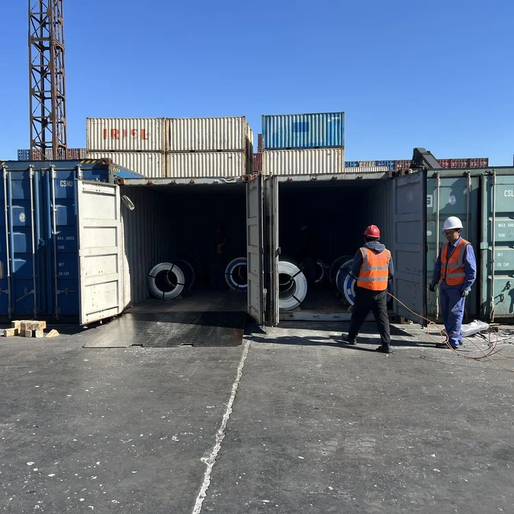
| Coil weight | Approx. 5 t per coil (mill or mother coil) |
| Coil inner diameter | 508 mm (20″) standard, 610 mm on request |
| Thickness tolerance | ± 4% of nominal thickness |
| Width tolerance | ± 1.0 mm on slit strip |
Stacking factor is easy to underweight in a spec review. It shouldn’t be. At 0.95 versus 0.97, a stack of 100 mm of gross lamination height carries roughly 2 mm less active steel — over a full core window, that gap shows up directly in the achievable flux and, downstream, in the core loss the finished transformer actually exhibits versus the datasheet number for the raw coil. We’ve had buyers spend weeks negotiating a 0.05 W/kg core-loss difference between two quotes while never asking either supplier for their stacking factor. Worth flipping that priority.
Ultra-thin CRGO for high-frequency cores
Standard 0.23–0.35 mm CRGO is optimized for 50/60 Hz power frequency. Above a few hundred hertz, eddy-current loss rises roughly with the square of lamination thickness, so cores running at 400 Hz, switching frequency, or aerospace power specs need a thinner gauge to stay efficient — which is why high-frequency and EV-charger designs use a separate ultra-thin line rated on a different reference point (P1.0/400 rather than P1.7/50):
| Grade | Thickness | Core loss P1.0/400 | Induction B8 | Typical use |
|---|---|---|---|---|
| GT-050 | 0.05 mm | ≤ 9 W/kg | ≥ 1.83 T | Highest-frequency cores, aerospace 400 Hz |
| GT-080 | 0.08 mm | ≤ 11 W/kg | ≥ 1.84 T | HF reactors and chokes |
| GT-100 | 0.10 mm | ≤ 14 W/kg | ≥ 1.85 T | EV onboard chargers, DC-DC converters |
| GT-150 | 0.15 mm | ≤ 19 W/kg | ≥ 1.86 T | Mid-frequency transformers |
| GT-200 | 0.20 mm | ≤ 25 W/kg | — | Lower-frequency HF applications |
Note the different test reference (1.0 T / 400 Hz instead of 1.7 T / 50 Hz) — the two loss figures aren’t directly comparable line-for-line against the standard CRGO table above, since they’re measured under different magnetizing conditions. If a datasheet quotes P1.0/400 alongside a P1.7/50 figure without saying so, that’s worth flagging before comparing numbers across suppliers.
How this compares internationally
Chinese GB/T 2521 grades aren’t the only naming system in circulation, and buyers sourcing globally usually want a sanity check against a second data source. JFE Steel Corporation, one of the largest global GOES producers, publishes very similar loss/induction pairings for its own equivalent lines: JFE’s 27JG120 (0.27 mm, conventional grain-oriented) is guaranteed at ≤1.20 W/kg core loss at 1.7T/50Hz with a minimum B8 of 1.80 T — in the same band as the 27Q120/M4 grade above — while its 23JGHE080 laser-domain-refined Hi-B grade is guaranteed at ≤0.80 W/kg with B8 ≥1.87 T, closely tracking the 23QG080 Hi-B numbers in the table above. That kind of cross-standard convergence is a useful check when qualifying a new supplier. If a claimed-equivalent grade lands far outside this range, ask why before you commit a purchase order — not after the coil is on a ship.
How Grain Orientation Is Achieved
The Goss texture doesn’t happen by accident — it’s the product of a specific hot-rolling, cold-rolling and high-temperature (around 1200°C) secondary recrystallization anneal that selectively grows grains with the [110]<001> orientation at the expense of every other orientation present after cold rolling. In broad strokes, the sequence runs: hot-rolled coil → normalizing/pickling → a first cold-rolling pass → an intermediate (decarburization) anneal that sets up the right grain-size and inhibitor distribution → a second cold-rolling pass to final gauge → a high-temperature box anneal (secondary recrystallization) where the Goss-oriented grains consume their neighbors and grow to millimeter scale → an insulating coating anneal that applies the glass/phosphate coating and relieves rolling stress at the same time.
Get any stage of that sequence wrong — rolling reduction ratio, intermediate anneal temperature, or final coating anneal atmosphere — and the resulting texture sharpness (and therefore B8) drops, which is exactly why B8 and core loss are the two numbers a mill test certificate exists to prove rather than assume. For the full six-step breakdown of how a coil goes from slab to finished CRGO, see how CRGO coil is made.
Applications
- Power transformers — M3/M4 (or Hi-B) grades where core efficiency losses compound over decades of continuous operation
- Distribution transformers — M5/M6 grades balance loss against cost for higher-volume, lower-duty-cycle installations
- Current and potential transformers — thin-gauge, low-loss grades where measurement accuracy depends on core behavior
- Reactors and magnetic amplifiers — same fixed-flux-path logic as transformers
Rotating machines — motors, generators, EV traction drives — use non-oriented electrical steel instead, because flux direction rotates through the lamination rather than following one fixed path.
What the Loss Numbers Cost You Over Time
It’s easy to treat the difference between an M4 core (≤1.20 W/kg) and a Hi-B 23QG090 core (≤0.90 W/kg) as a rounding error on a datasheet. In an operating transformer it isn’t. Core loss is a no-load loss — it’s dissipated continuously, 24/7, for as long as the transformer is energized, regardless of whether it’s under load. A distribution transformer built with standard-grade steel instead of Hi-B can carry a meaningfully higher no-load loss across its full service life, and utilities and large industrial buyers increasingly weight that lifetime energy cost — not just the purchase price of the core steel — when comparing bids. That’s the calculation behind regulatory pushes like updated DOE and EU ecodesign efficiency minimums, and it’s why Hi-B and laser-scribed material, despite a per-tonne price premium, keeps gaining share in new transformer designs rather than losing it to cheaper standard grades.
So don’t stop at price per tonne. Multiply the quoted core loss by the transformer’s expected duty cycle and your local electricity cost, then weigh that lifetime loss cost against the steel price delta. It’s a five-minute spreadsheet exercise that changes which grade actually wins.
Mill Certificates and Grade Traceability
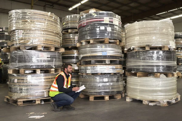
A datasheet only tells you what a mill claims to produce, not what’s actually in a given coil sitting on a truck. Every order should ship with a mill test certificate — most international buyers specify EN 10204 3.1 (test results traceable to the actual production batch) rather than 3.2 (which additionally requires a third-party or customer witness). Here’s the uncomfortable part: prime and secondary/off-grade CRGO can carry visually similar coil wrapping. The coil edge doesn’t tell you whether the loss number on the paperwork is real. Confirm grade traceability and test certificate authenticity before accepting a shipment, not after it’s already through your slitting line — our prime vs. secondary CRGO guide walks through the checks that catch mismatched material early.
Customization Options
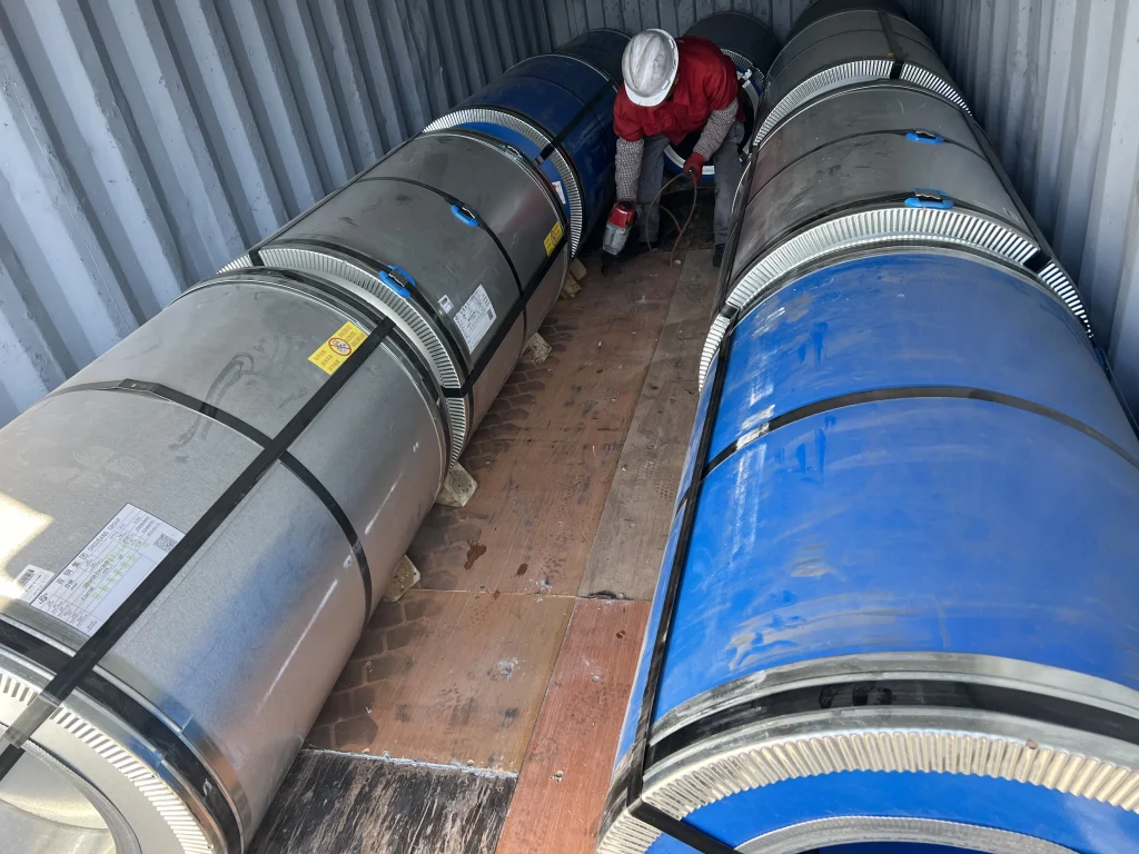
Coil can be supplied as full-width mill coil or slit to width (8–1,250 mm), cut-to-length sheet, or with alternative coatings (C6 inorganic-organic) where higher interlaminar resistance or punchability is required. Free samples are typically available within about a week so core loss and stampability can be verified before committing to a production order.
FAQ
What does “P1.7/50” mean on a CRGO datasheet?
P1.7/50 is the specific core (iron) loss measured at a peak magnetic induction of 1.7 tesla and a frequency of 50 Hz, expressed in watts per kilogram. It’s the standard reference point for grain-oriented electrical steel because 1.7 T sits close to typical transformer core operating flux density; a lower P1.7/50 number means less energy wasted as heat per kilogram of core steel.
What is B8 and why does it matter?
B8 is the magnetic induction (in tesla) measured at a magnetizing field strength of 800 A/m — effectively a proxy for how sharply the grain orientation has been achieved. A higher B8 means the steel saturates at a higher flux density along the rolling direction, which lets a designer either shrink the core for the same rating or hold the core size and gain efficiency headroom.
Why does stacking factor matter if I already know the loss and induction numbers?
Stacking factor measures how much of a laminated stack’s gross height is actually steel versus coating and air gaps between sheets. Two coils with identical loss and B8 specs can still yield different finished-core performance if their stacking factors differ, because a lower stacking factor means less active steel — and therefore less flux-carrying capacity — inside the same physical core window.
Should I choose Standard CRGO or Hi-B/laser-scribed CRGO?
If you’re not sure, start with Standard CRGO — it’s the default for a reason and covers most power and distribution cores without over-specifying. Move to Hi-B or laser-scribed only when something forces the question: a regulatory efficiency minimum you have to clear, or a duty cycle high enough that the loss premium pays for itself within a few years rather than a decade. Run the numbers on your own project rather than defaulting to “premium is always better” — see the Hi-B vs. standard CRGO payback comparison for a worked example.
Can grades be matched across GB, JIS, AISI and IEC standards?
Yes, though the standards measure against different reference points (1.5T vs. 1.7T, 50Hz vs. 60Hz), so a direct grade-code match isn’t always exact — it’s a matter of confirming the closest equivalent loss/induction pairing. Sending your existing spec or datasheet for cross-reference is more reliable than matching grade codes alone.

