
Interlaminar resistance is the electrical resistance of the insulating coating between two neighbouring laminations, and on most mill certificates it appears as a Franklin test value in Ω·cm². It decides whether eddy currents stay inside each sheet or find a path across the stack. This guide explains how the number is measured, what values each coating class typically reaches, what lowers it once the steel is punched and stacked, and how to write it into an order.
Coating classes themselves (C-2, C-3, C-5 and so on) are covered in our guide to electrical steel coating types. This article is about the number that proves a coating is doing its job.
| Coating (ASTM A976 class) | Typical use | Stated minimum, Franklin test |
|---|---|---|
| Organic, C-3 | Interlocked, riveted or clamped motor and small transformer cores | > 5 to > 50 Ω·cm² per lamination, rising with thickness |
| Phosphate, C-4 | Welded cores, die-cast rotors, cores that are annealed | > 5 Ω·cm² per lamination |
| Inorganic-organic, C-5 | General motor and generator cores; welding and annealing | > 2 to > 50 Ω·cm² per lamination, rising with thickness |
| C-5 over glass film (C-2), grain-oriented | Transformer cores | > 10 Ω·cm² |
The non-oriented figures come from thyssenkrupp’s stabolit product information (2022). The grain-oriented figure is the one thyssenkrupp states for its POWERCORE coating. Other mills publish different numbers for the same class, which is why the order has to name a value, not just a class.
How the Franklin Test Works
The Franklin tester presses ten small contacts onto the coated surface of a single sheet and applies 0.5 V between each contact and the steel underneath. It then reads the total current. A US patent on insulation testing describes the scale: a fully conductive sheet gives a “Franklin current” of 1 A, and a perfectly insulated sheet gives 0 A. The current is converted into a surface insulation resistivity in Ω·cm². Lower current means better insulation.
The method appears under three names that buyers will see on paperwork:
- ASTM A717 in the US, which reports Ω·cm² per lamination
- IEC 60404-11 internationally (EN IEC 60404-11 in Europe). The second edition, published in 2021, added a way to measure both sides of a specimen without reinserting it
- JIS C 2550 in Japan. JFE Steel’s catalogue lists its test conditions as ten electrodes of 1 cm² each, 0.5 V DC and a pressure of 2 N/mm²
China’s GB/T 2522-2017 covers coating insulation resistance and coating adhesion together. It was drafted with reference to IEC 60404-11 but is marked as not equivalent, so check which standard a certificate cites before comparing two suppliers.
A different method, ASTM A937, measures the resistance between two coated surfaces placed against each other and reports it in kΩ. ASTM states it is not the same quantity as the Franklin result, so do not compare an A937 number with an A717 number.
Single readings scatter. The same patent notes that surface resistivity can vary by 50% or more from one place to another on a sheet, and ASTM’s summary of A937 gives the reason: coating thickness varies across a lamination. A useful figure is an average of several readings taken across the strip width. Interlaminar resistance sits alongside core loss and polarisation as a routine lab check; our article on Epstein frame core loss testing covers the magnetic side.
What Values Do Coating Classes Reach?
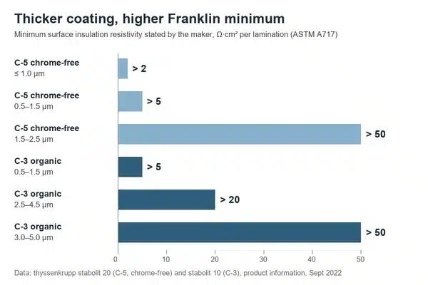
It depends far more on coating thickness than on the class name. thyssenkrupp’s stabolit data shows this clearly. Its chrome-free C-5 coating is stated at more than 2 Ω·cm² per lamination when it is 1.0 µm or thinner, and more than 50 Ω·cm² at 1.5–2.5 µm. Its organic C-3 goes from more than 5 to more than 50 Ω·cm² as the coating goes from 0.5–1.5 µm to 3.0–5.0 µm.
Other published figures for the same class sit far apart:
- ArcelorMittal states at least 2 Ω·cm² per side for its thinnest C5 coating (1 µm or less), and at least 3 Ω·cm² per side for its C5-T, measured by Franklin test to EN 60404-11.
- Arnold Magnetics requires a C-5 coating with a minimum of 10 Ω·cm² per lamination by ASTM A717 on its thin slit strip.
- Quaker Houghton’s lab data for its EVERTREAT 2050 C5 coating shows 4,000 to 20,000 Ω·cm² below 1.5 µm, and adds that results are “highly substrate and substrate roughness dependent.”
The spread is the point. A class name does not fix a number, and a lab value on a coating supplier’s test panel is not the same as a minimum on coated coil. For non-oriented motor steel, the coating and its insulation value are listed with each grade on our non-oriented silicon steel page.
Per Side, Per Lamination or kΩ?
Read the unit before the number. Three conventions appear on certificates and datasheets:
| How it is written | Where you see it | What to check |
|---|---|---|
| Ω·cm² per lamination | ASTM A717 results, US datasheets | The standard’s own reporting basis |
| Ω·cm² per side | Some European datasheets | Ask whether the figure is the same measurement reported per surface |
| kΩ | ASTM A937 two-surface test | A different quantity; not comparable with Franklin results |
When a certificate gives only a class (for example “C-5”) and no value, the insulation was either not tested on that lot or not reported. If your design depends on a minimum, ask for it to be printed. Our article on EN 10204 3.1 and 3.2 certificates explains which test results a 3.1 certificate should carry.
What Lowers Interlaminar Resistance in the Core?
The value on the certificate is measured on a flat, clean, unstressed sheet. The finished core is none of those things. Four things pull the number down.
Clamping pressure and heat. The US patent cited above says surface resistivity of an unclamped lamination ranges from 1 to 200 Ω·cm² depending on coating thickness, and that clamping pressure can reduce it by nearly 50%. Operating temperature lowers it further.
Burrs. A punching burr can cut through the coating of the next sheet. Shah and colleagues at Aalto University describe how burrs “impair the insulation of adjacent sheet and make random galvanic contacts during pressing.” If burrs touch on opposite edges of a stack, or the stack is welded or bolted, current can circulate through those paths. They cite an earlier experiment in which burr contacts raised loss by up to 5% of total loss. Burr limits for stamped laminations are covered in our motor lamination stamping guide.
Welding, cleating and full-face bonding. A weld seam connects every sheet it crosses. Kansai Helios lists “short circuits” among the disadvantages of welded stacks in its 2026 coatings presentation. Bonding avoids weld seams, but thyssenkrupp notes for its stabolit 70 bonding varnish that, depending on the pressure applied, some direct contact between laminations may occur during bonding. Our comparison of lamination stacking methods shows how much loss each joining method adds.
Annealing in the wrong atmosphere. Nippon Steel says its non-oriented coatings withstand stress relief annealing up to about 800 °C in a non-oxidising atmosphere, and warns that care is needed so the atmosphere does not become oxidising. An organic C-3 coating is not built for annealing at all; thyssenkrupp rates its C-3 stabolit 10 at 180 °C continuous in air.
How Much Interlaminar Resistance Does a Core Need?
More for large machines, less for small ones. A 2016 patent filing by JFE Steel and Dai Nippon Toryo states that steel for large generator cores needs a larger interlaminar insulation resistance than steel for small motors, and that the value should stay high after exposure to high temperature. An earlier Armco patent says the same of non-oriented steel for medium and large motors, generators and transformers: it needs a coating with high surface resistivity “to minimize interlaminar power losses,” and that this may also be required after stress relief annealing.
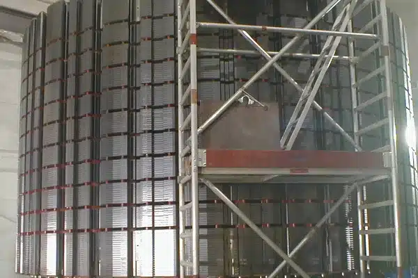
The reason is size. A short, interlocked stator for a small motor has a short path for any current that leaks between sheets. A generator stator several metres across, or a large rotor stack like the one in the cover photo, gives that current a long loop and a lot of area to cross. The basic reason cores are built from insulated sheets in the first place is explained in our article on why transformer cores are laminated.
As a rough guide:
- Small interlocked or welded motors: a thin C-5 or C-4 for punchability and weldability; a few Ω·cm² is normal.
- Medium motors and small transformers, clamped or riveted: a thicker C-3 or C-5; tens of Ω·cm².
- Large generators and hydro or wind machines: a thick C-5 or C-6, with the minimum stated after any heat treatment the core will see.
- Grain-oriented transformer cores: the mill’s C-5-on-glass-film coating, typically stated at more than 10 Ω·cm².
Why Chrome-Free Coatings Mean Re-checking the Spec
Because the chemistry is changing, and the number has to be confirmed again for each new coating. Coating suppliers now present chrome-free products as standard. Kansai Helios describes its Remisol core plate varnishes as “100% chrome-free” in a presentation published in May 2026, and Quaker Houghton says its chrome-free technology “supports the latest legislative requirements.”
The regulatory pressure is real. In April 2025 the European Chemicals Agency proposed restricting certain chromium(VI) substances, with exceptions for listed uses, including surface treatment, that meet worker-exposure and emission limits. In June 2026 ECHA opened a 60-day consultation on the draft opinion of its socio-economic committee, with comments due by 17 August 2026. The final scope has not been settled yet.
For interlaminar resistance, two things follow:
- Chrome-free can match chrome-containing coatings. thyssenkrupp says its chromium-containing and chromium-free POWERCORE coatings are “similar from a technological point of view,” both stated at more than 10 Ω·cm².
- But values change with the formulation. thyssenkrupp’s own chrome-free C-5 for non-oriented steel starts at more than 2 Ω·cm² in its thinnest form. A switch of coating at the mill is a reason to re-qualify the insulation value, not to assume it.
What to Write on the Order
A useful insulation spec has six parts. “C-5 coating” alone is only one of them.
| Order item | Example | Why |
|---|---|---|
| Coating class and chemistry | C-5, chrome-free | Sets punchability, weldability and anneal resistance |
| Coating thickness per side | 1.0–1.5 µm | Drives both the insulation value and the stacking factor |
| Minimum insulation value and unit | ≥ 10 Ω·cm² per lamination | A number you can reject a coil against |
| Test standard | ASTM A717, IEC 60404-11 or GB/T 2522 | Results from different methods are not comparable |
| Test condition | As coated, or after anneal at a stated temperature | Matters if the core is stress relief annealed |
| Sampling | Average of readings across the width, per coil or per lot | Single readings scatter |
If your laminations will be stress relief annealed, our guide to stress relief annealing lists which coating classes survive the furnace.
We supply non-oriented and grain-oriented electrical steel with C-3, C-5 or the mill’s standard grain-oriented coating. Send us your minimum insulation value and test standard, and we’ll confirm the matching coating before quoting. Our CRNGO steel coil page lists the grades and coatings available. Coil orders typically start at about 5 tonnes with delivery in about 15 days, and smaller lots can be cut from coil. Sheet orders typically start at about 500 kg; if you need less, tell us and we’ll do our best to meet the request. Samples typically cost USD 200 including freight, refunded when you place a production order.
FAQ
What is interlaminar resistance in electrical steel?
It is the electrical resistance of the insulating coating between two neighbouring laminations in a core. It keeps eddy currents inside each sheet instead of letting them flow across the stack. Mills usually report it as a surface insulation resistivity from the Franklin test, in Ω·cm² per lamination or per side, measured on a single coated sheet.
What is a good Franklin test value?
It depends on the core. Thin C-5 or C-4 coatings for small interlocked or welded motors are often stated at a few Ω·cm². Clamped motor and small transformer cores use thicker coatings in the tens of Ω·cm². Grain-oriented transformer coatings are typically stated above 10 Ω·cm². Large generators need the highest values, confirmed after any heat treatment.
Is the Franklin test the same as ASTM A937?
No. The Franklin test (ASTM A717, IEC 60404-11) measures one coated surface of a single sheet through ten contacts and reports Ω·cm². ASTM A937 measures the resistance between two coated surfaces pressed together and reports kΩ. ASTM states the two are different quantities, so a value from one method cannot be checked against a limit written for the other.
Does stress relief annealing reduce interlaminar resistance?
It can. Inorganic and inorganic-organic coatings are built to survive annealing, and Nippon Steel rates its non-oriented coatings to about 800 °C in a non-oxidising atmosphere. An oxidising atmosphere can damage them. Organic C-3 coatings are not meant for annealing. If the core is annealed, state the minimum insulation value after the anneal on the order.
Do chrome-free coatings have lower insulation resistance?
Not necessarily. thyssenkrupp states the same value, more than 10 Ω·cm², for its chromium-containing and chromium-free grain-oriented coatings. What changes the number most is coating thickness and formulation. When a mill switches to a chrome-free coating, ask for its Franklin values at your coating thickness rather than assuming the old figure still applies.
Need coated coil with a stated insulation value? Contact us with the grade, gauge, coating class, minimum Franklin value and test standard, and we’ll confirm the coating before quoting.
References
- thyssenkrupp Steel, September 2022 — stabolit insulation coatings for non grain oriented electrical steel: product information
- thyssenkrupp Steel — POWERCORE grain-oriented electrical steel: insulation types
- D. K. Rao, US Patent 8,289,031 B1, 2012 — Apparatus for measuring insulation characteristics of coated steel sheet
- IEC 60404-11:2021 — Magnetic materials, Part 11: methods of measurement of the surface insulation resistance of electrical steel strip and sheet (AFNOR catalogue)
- ASTM A937/A937M-12(2019) — Standard test method for determining interlaminar resistance of insulating coatings using two adjacent test surfaces
- GB/T 2522-2017 — Methods of test for the determination of coating insulation resistance and coating adhesion of electrical strip and sheet (catalogue page)
- JFE Steel — Non-oriented electrical steel sheets catalogue F1E-001
- Nippon Steel, 2020 — Non-oriented electrical steel sheets catalogue D005je
- ArcelorMittal — iCARe electrical steel coatings
- Arnold Magnetics, SP-RP-0001 rev. 30 April 2024 — Tolerances for coated slit and as-rolled edge silicon steel
- Quaker Houghton — Insulating coatings for non-grain oriented electrical steel used in laminated cores
- A. Kolm, F. Lober, C. Weissensteiner, S. Helfert (Kansai Helios), Electrical Steel Summit, 2026 — Pushing the limits of electrical steel bonding
- S. B. Shah, P. Rasilo, A. Belahcen, A. Arkkio, Electrical, Control and Communication Engineering 3, 2013 — Modeling of losses due to inter-laminar short-circuit currents in lamination stacks
- Armco Inc., US Patent 5,955,201, 1999 — Inorganic/organic insulating coating for nonoriented electrical steel
- JFE Steel and Dai Nippon Toryo, EP 3040444 A1, 2016 — Electromagnetic steel sheet with insulating coating film
- European Chemicals Agency, 29 April 2025 — ECHA proposes restrictions on chromium(VI) substances to protect health
- Ibec, 30 June 2026 — European Chemical Agency consultation
Image credits
- Goldisthal rotor lamination stack: Mazbln, Wikimedia Commons, CC BY-SA 3.0
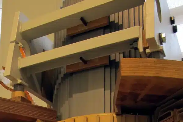
- Transformer limb with stepped core: Tmw11w1 (Technisches Museum Wien), Wikimedia Commons, public domain


