
Transformer core laminations, EV motor stator stampings, and generator core punchings all begin the same way: as wide electrical steel coils that must be slit to precise widths before being cut to their final shape. Precision slitting — the process of longitudinally cutting master coils into narrower strips — is a critical upstream step that determines whether your downstream stamping or laser-cutting process can achieve the dimensional tolerances your design demands. This guide explains how precision electrical steel slitting works, what specifications to provide for an OEM/ODM order, and what quality parameters to verify.
One clarification up front: this page is about a steel-processing service, not industrial equipment. We slit steel — we do not build, sell or export slitting lines, slitters, or other coil-processing machinery. If you’re sourcing a slitting line for your own factory rather than ordering electrical steel that’s already slit to width, we’re not the right supplier for that.
Core Key Points
- Precision slitting converts wide master coils (typically 800–1,250 mm wide) into narrow strips to the exact widths required for your transformer core lamination or motor stator stamping die.
- Width tolerance achievable on modern CNC slitting lines is ±0.05–0.10 mm — a critical parameter for step-lap transformer core construction and precision motor stator dies.
- For transformer core applications, slit width must match the step-lap lamination design precisely; for motor stator applications, slit width determines the strip width entering the progressive stamping die.
- Zhongxin Steel’s OEM/ODM slitting service can produce 20–1,000 mm slit widths from standard CRGO and CRNGO master coils, with 5-business-day turnaround from stock.
- Burr height on slit edges (ideally < 0.01 mm per IEC standards for motor laminations) is as important as width tolerance — specify burr limits in your order.
- Custom slit coil weight and inner diameter should be specified to match your decoiling/uncoiling equipment capacity.
What Is Electrical Steel Slitting and Why It Matters
The Role of Slitting in Electrical Steel Processing
Electrical steel is produced in wide coils (800–1,250 mm) because wide production equipment is more economical for the steel mill. However, nearly all downstream applications require narrower strip:
- Transformer cores: Step-lap cores require multiple different lamination widths (e.g., 750 mm, 625 mm, 500 mm, and 375 mm for a four-step core) cut from a master coil.
- Motor stator stamping: Progressive dies typically accept strip widths of 100–400 mm matching the stator OD plus minimal scrap web.
- Generator cores: Large generator stator punchings may use strips up to 600–800 mm wide.
Slitting is not a simple cutting process — it requires precision tooling, controlled tension, and quality control to achieve the width tolerance, edge quality, and flatness that downstream processes demand.
Why Slitting Quality Affects Your Final Product
Poor slitting quality propagates into every downstream step:
- Width variance → Core lamination doesn’t fit precisely → Air gaps in step-lap joints → Higher no-load losses
- Burr on slit edges → Inter-laminar shorting in stacked cores → Increased eddy-current losses
- Edge camber (strip not straight) → Misalignment in progressive die → Geometry errors in lamination → Motor performance variation
- Surface damage from slitting knives → Coating damage → Insulation breakdown between laminations
The Slitting Process: Step by Step
Step 1: Coil Preparation
The master coil is loaded onto a decoiler (uncoiler) that supports the coil’s inner diameter and controls tension during uncoiling. Master coil weights for electrical steel typically range from 3,000–8,000 kg.
The coil is threaded through a straightening roller section to remove coil set (the natural curvature from coil storage) before entering the slitter.
Step 2: CNC Slitting
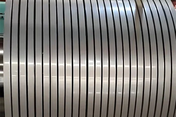
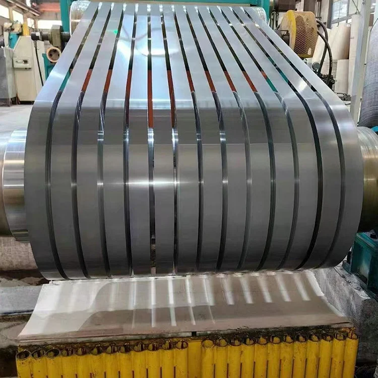
The slitting head contains precision circular knives (slitting knives) arranged in pairs. Each pair of knives creates one longitudinal cut. A single slitting pass can create multiple strips simultaneously (typically 3–20 strips from one master coil pass depending on strip widths).
Critical parameters:
- Knife gap (clearance): Typically 5–8% of material thickness. Too large → excessive burr height; too small → knife wear, potential cracking.
- Knife overlap (penetration): The depth the upper and lower knives overlap into the material plane.
- Speed: 50–200 m/min for electrical steel, depending on thickness and grade. Thinner material requires slower speeds to control tension.
Modern slitting lines use CNC positioning of knives to ±0.01 mm, enabling width tolerances of ±0.05 mm on finished strip.
Step 3: Recoiling
After slitting, the individual strips are recoiled onto separate coil mandrels. For narrow strips (< 100 mm), separators are placed between adjacent coils during winding to prevent “telescoping” (coil shifting laterally during winding).
Recoil parameters to specify:
- Inner diameter: typically 500–600 mm (smaller for narrow strips)
- Outer diameter: typically 1,000–1,800 mm
- Coil weight: typically 500–3,000 kg per slit coil
Step 4: Quality Inspection and Packaging
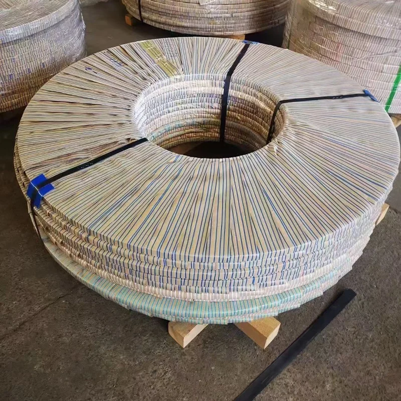
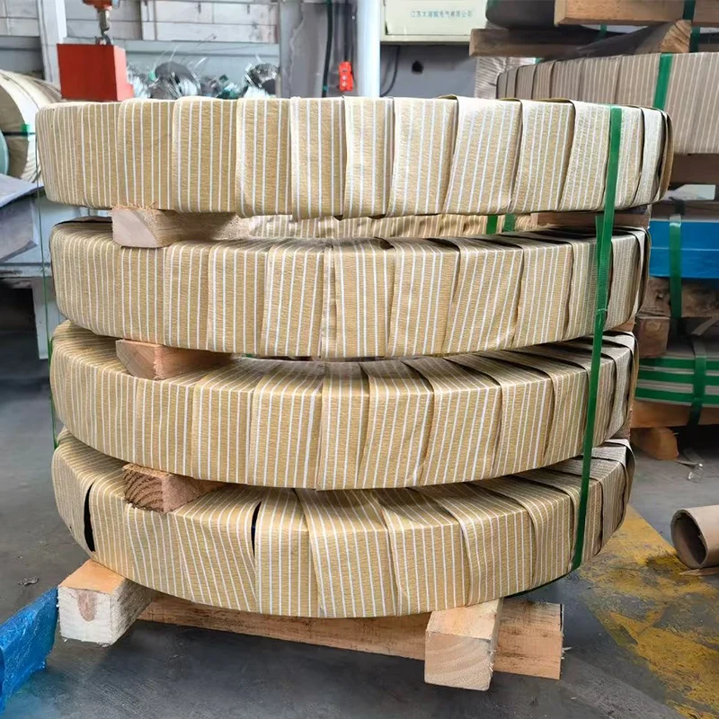
After recoiling, each slit coil undergoes dimensional inspection (width measured at multiple points, inner/outer diameter, weight). Surface inspection confirms coating integrity on both sides. Each coil is wrapped in protective packaging (VCI polyethylene film, corrugated steel protection rings) for shipment.
Width Tolerance and Quality Standards
Width Tolerance Standards
| Tolerance Class | Width Tolerance | Applicable Standard | Typical Application |
|---|---|---|---|
| Normal | ±0.3 mm | IEC 60404-8-7 (General Tolerance) | Distribution transformer cores, Class A applications |
| Precision | ±0.1 mm | IEC 60404-8-7 (Table 4) | Step-lap transformer cores, power transformer applications |
| Ultra-precision | ±0.05 mm | Customer specification / Customized requirements | Step-lap cores, AA0 class high-efficiency transformers |
| EV Motor | ±0.05 mm | IATF 16949 applicable requirements | Motor stator stamping dies, electric vehicle drive motors |
Burr Height Standards
Burr height on slit edges determines inter-laminar insulation quality:
| Application | Maximum Burr Height | Standard Reference |
|---|---|---|
| Standard Transformer Laminations | < 0.05 mm | IEC 60404-8-7 |
| Motor Stator Stamping | < 0.01 mm | IEC 60404-11 Recommendation |
| Ultra-thin EV Motor (< 0.20 mm) | < 0.005 mm | OEM Specification |
Note: Burr height < 0.01 mm (10 µm) is achievable only with new or freshly-ground knives. Knife wear monitoring is critical for consistent burr quality.
Camber (Strip Straightness)
Strip camber is the lateral deviation of the strip from a straight line, measured over a 2-meter length:
- Standard tolerance: ≤ 1.5 mm / 2 m
- Precision tolerance: ≤ 0.5 mm / 2 m
- For progressive motor stamping dies: ≤ 0.3 mm / 2 m (some OEM specifications)
Specifying Your OEM/ODM Slitting Order
When placing a custom slitting order, provide the following specifications:
Required Specifications
| Parameter | Example | Notes |
|---|---|---|
| Input Grade | B27G100 Hi-B CRGO | Include IEC grade designation |
| Input Thickness | 0.27 mm ±0.005 mm | Original master coil specification |
| Slit Width(s) | 750 mm, 620 mm, 495 mm | Multiple widths possible per slitting pass |
| Width Tolerance | ±0.05 mm | Or reference applicable standard tolerance class |
| Quantity per Width | 50 tonnes at 750 mm, 30 tonnes at 620 mm | Specify quantity according to each width requirement |
| Coil Inner Diameter (Output) | 500 mm | Must match uncoiler mandrel requirements |
| Coil Outer Diameter Limit | ≤ 1,500 mm | Must comply with storage and transportation limitations |
| Maximum Coil Weight | 2,000 kg | Must match decoiler / handling equipment capacity |
Optional Specifications
- Burr height limit: Specify if standard is insufficient (e.g., < 0.008 mm for thin gauge motor applications)
- Edge conditioning: Deburring pass requested (adds step and cost but reduces burr)
- Surface coating: Confirm coating type must be preserved without damage
- Special packaging: Sealed VCI packaging, wooden pallet dimensions, strap type (plastic preferred to avoid coating damage)
Common Slitting Configurations for Transformer vs. Motor Applications
Transformer Core Slitting (Step-Lap Design)
A 3-phase 630 kVA transformer core in a 4-step step-lap design might require:
| Step | Lamination Width | % of Main Limb Width | Strip Count |
|---|---|---|---|
| Step 1 (Center) | 240 mm | 100% | 1 |
| Step 2 | 215 mm | 90% | 2 |
| Step 3 | 185 mm | 77% | 2 |
| Step 4 (Outer) | 145 mm | 60% | 4 |
Each of these widths must be slit to ±0.05 mm to ensure precise step overlap in the assembled core. Zhongxin Steel can slit all required widths from the same CRGO master coil in multiple passes, ensuring consistent grade and heat across all lamination widths.
Motor Stator Slitting (Progressive Die)
For a CRNGO motor stator progressive stamping die:
| Parameter | Typical Value |
|---|---|
| Stator OD | 200 mm (example) |
| Web width (scrap) | 15 mm each side |
| Required strip width | 200 + 15 + 15 = 230 mm |
| Width tolerance | ±0.05 mm |
| Edge condition | Deburring recommended |
| Slit coil weight | ≤ 2,000 kg (to limit die change frequency) |
Quality Verification: What to Inspect on Delivery
Upon receipt of custom-slit electrical steel, conduct these incoming inspections:
- Width measurement — Measure width at ≥ 5 points along the first 10 meters of strip. Compare against order specification and tolerance.
- Coil identification — Verify each coil’s label matches the MTC data (coil number, grade, original master coil reference).
- Surface condition — Inspect for coating damage (scratches > 5 mm length), rust spots, or slitting knife marks.
- Edge quality — Check burr height with micrometer or surface profilometer at 3 points per coil edge.
- Flatness check — Unroll 2 meters on a flat surface; strip should lie flat without consistent camber.
Lead Times and Minimum Order Quantities
| Service Type | Lead Time (from Order Confirmation) | Minimum Order Quantity |
|---|---|---|
| Standard Grades from Stock (CRGO B30G120, B27G100; CRNGO 35W300) | 5–7 Business Days | 5 tonnes per slit width |
| Non-stock Grades (Sourced to Order) | 4–8 Weeks | 20 tonnes per grade |
| Ultra-thin Grades (0.10–0.20 mm) | 8–12 Weeks | 3 tonnes per slit width |
| Trial Samples for Qualification | 2–3 Weeks | 100 kg per width |
For urgent requirements, Zhongxin Steel can accommodate expedited slitting on stock grades with 48–72 hour turnaround for confirmed orders above 10 tonnes.
FAQ
Do you manufacture or sell slitting line equipment?
No. Zhongxin Steel is an electrical steel mill — we run our own CNC slitting lines in-house to process the CRGO and CRNGO coil we supply, but we don’t design, manufacture, sell or export slitting machinery, slitters, or other coil-processing equipment. If you’re looking to buy a slitting line for your own factory rather than order electrical steel that’s already slit to width, this page — and this supplier — isn’t what you’re after.
Can I order custom-slit electrical steel in mixed widths from a single master coil?
Yes. A single slitting pass can produce multiple different widths simultaneously, as long as the sum of slit widths plus knife thicknesses (typically 1–2 mm total) does not exceed the master coil width. For example, from an 1,050 mm master coil: 750 mm + 280 mm + tolerances/scrap = feasible in one pass. This is the most cost-efficient approach for transformer builders who need multiple step widths.
What is the difference between slitting and cut-to-length for electrical steel?
Slitting cuts longitudinally (along the coil length) to produce narrow continuous strips. Cut-to-length cuts transversely (across the width) to produce flat sheets of a specific length. Most transformer laminations require both operations: slitting first (to the lamination width), then cut-to-length (to the lamination length). Motor stator laminations use progressive die stamping from strip, which handles cut-to-length internally during stamping.
Does slitting change the magnetic properties of electrical steel?
The slitting process itself does not change the bulk magnetic properties of the steel — the cutting is mechanical, not thermal. However, the cut edges (within 5–10 mm of the slit line) experience work hardening that locally degrades magnetic properties. This edge effect is why transformer lamination widths and motor stator punchings are designed with sufficient web so that the final magnetic circuit is not in the affected edge zone.
What certification does Zhongxin Steel hold for its slitting service?
Zhongxin Steel’s slitting operations are covered under its ISO 9001:2015 quality management system certification. The slitting service is available for grades compliant with IEC 60404-8-7 (CRGO) and IEC 60404-8-4 (CRNGO). On-site Epstein Square testing is available for verification of slit coil material against original grade specifications.
References
- IEC 60404-8-7:2008+AMD1:2011 — Cold-rolled grain-oriented electrical steel strip and sheet delivered in the fully-processed state. Geneva: IEC.
- IEC 60404-8-4:2022 — Cold-rolled non-oriented electrical steel strip and sheet delivered in the fully-processed state. Geneva: IEC.
- Roberts, W. L. (1983). Cold Rolling of Steel. New York: Marcel Dekker.
- Beckley, P. (2002). Electrical Steels for Rotating Machines. Stevenage: IEE.
- ASTM A34/A34M-21 — Standard Practice for Sampling and Procurement Testing of Magnetic Materials. West Conshohocken: ASTM.


